FUEL INJECTOR (w/ DPF) REMOVAL
Note
-
When replacing the injectors (including shuffling the injectors between the cylinders), common rail or cylinder head, it is necessary to replace the injection pipes with new ones.
-
When replacing the fuel supply pump, common rail, cylinder block, cylinder head, cylinder head gasket or timing gear case, it is necessary to replace the fuel inlet pipe with a new one.
-
After removing the injection pipes and fuel inlet pipe, clean them with a brush and compressed air.
-
CHECK FOR INJECTOR COMPENSATION CODE
Tech Tips
If the injector compensation code is not correctly registered, it may cause malfunctions.
-
Read the injector compensation code Click here.
-
Check that the compensation code of the installed injector is the same as the code registered in the ECM. If the code is not the same, register the injector compensation code on the injector Click here.
-
-
DISCONNECT CABLE FROM NEGATIVE BATTERY TERMINAL
-
REMOVE ELECTRIC EGR CONTROL VALVE ASSEMBLY
-
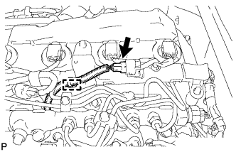
REMOVE NO. 3 NOZZLE LEAKAGE PIPE
-
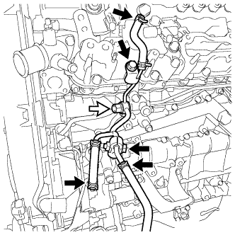
Disconnect the 3 fuel hoses.
-
Remove the fuel check valve and gasket from the No. 3 nozzle leakage pipe.
Text in Illustration 
Fuel Check Valve -
Remove the bolt and No. 2 injection pipe clamp from the No. 3 nozzle leakage pipe and No. 3 fuel pipe.
-
Remove the bolt and No. 3 nozzle leakage pipe.
-
-
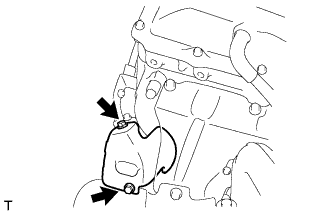
REMOVE NO. 2 EXHAUST MANIFOLD HEAT INSULATOR
-
Remove the 2 bolts and No. 2 exhaust manifold heat insulator.
-
-
REMOVE NO. 3 FUEL PIPE
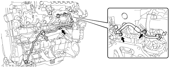
Text in Illustration Union Bolt 
Fuel Check Valve 
Bolt - -
-
Remove the 2 union bolts and gasket from the No. 3 fuel pipe.
-
Remove the fuel check valve and gasket from the No. 3 fuel pipe.
-
Remove the 3 bolts and No. 3 fuel pipe.
-
-
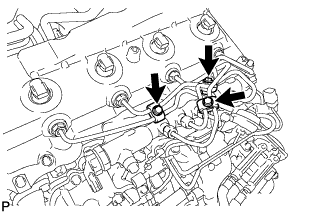
REMOVE NO. 2 NOZZLE LEAKAGE PIPE ASSEMBLY
-
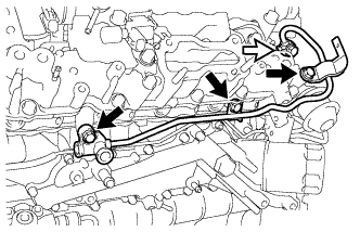
Remove the union bolt and gasket from the No. 2 nozzle leakage pipe assembly.
Text in Illustration Union Bolt -
Remove the 3 bolts and No. 2 nozzle leakage pipe assembly.
-
-
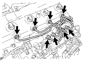
SEPARATE ENGINE WIRE
-
Disengage the wire harness clamp, separate the glow plug connector.
-
Disconnect the 10 connectors.
-
Remove the 4 bolts.
-
Disengage the 4 wire harness clamps, separate the engine wire.
-
-
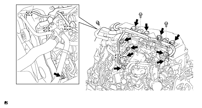
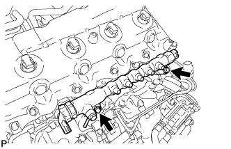
REMOVE INJECTION PIPE SUB-ASSEMBLY
-
Remove the 3 bolts and 3 No. 2 injection pipe clamps.
-
Using a union nut wrench 17 mm, remove the No. 1 to No. 4 injection pipe sub-assembly.
-
-
REMOVE NO. 1 INTAKE MANIFOLD INSULATOR
-
Remove the No. 1 intake manifold insulator from the intake manifold.
-
-
REMOVE COMMON RAIL ASSEMBLY
-
Remove the 2 bolts and common rail assembly.
-
-
REMOVE NO. 1 CYLINDER HEAD COVER SILENCER
-
Remove the No. 1 cylinder head cover silencer from the cylinder head cover sub-assembly.
-
-
REMOVE CYLINDER HEAD COVER SUB-ASSEMBLY
-
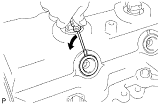
Using a small screwdriver, remove the nozzle holder seal by prying between the nozzle holder seal and the cutout part of the cylinder head cover.
-
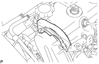
Disconnect the ventilation hose from the cylinder head cover sub-assembly.
-
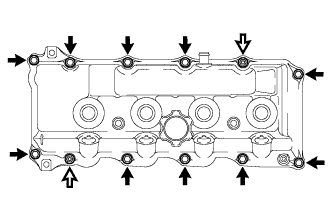
Remove the 10 bolts, 2 nuts, cylinder head cover sub-assembly and the cylinder head cover gasket.
Text in Illustration Bolt Nut -
Remove the 4 No. 3 cylinder head cover gaskets from the cylinder head cover sub-assembly.
-
-
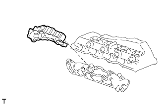
REMOVE FUEL INJECTOR
-
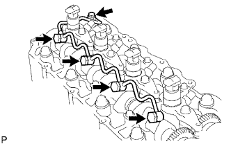
Remove the union bolt, 4 injector hollow screws, 5 gaskets and nozzle leakage pipe.
Note
-
When removing the nozzle leakage pipe, place a cushion under the pipe.
-
Be careful not to deform or scratch the union seal surface.
-
After removing the nozzle leakage pipe, put it in a plastic bag to prevent foreign matter from contaminating its injector inlet.
-
-
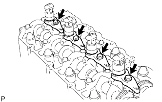
Remove the 4 bolts, 4 washers, 4 No. 1 nozzle holder clamps and 4 injectors.
Tech Tips
Arrange the injectors, No. 1 nozzle holder clamps, washers and bolts in the correct order.
-
Remove the O-ring from each injector.
-
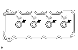
Remove the 4 injection nozzle seats from the cylinder head.
-