FUEL SUPPLY PUMP REMOVAL

-
DISCONNECT BATTERY NEGATIVE TERMINAL
Note
-
When removing the injection pipes and fuel inlet pipe, clean them up with a brush and compressed air.
-
When installing, clean up the seal surface of the injector, injection pipe, fuel inlet pipe, supply pump and common rail with clean light oil.
-
When replacing the common rail and/or injectors, it is necessary to replace injection pipes, as well.
-
When replacing the injection pump and/or common rail replaced, it is necessary to replace fuel inlet pipe, as well.
-
-
REMOVE FRONT SEAT ASSEMBLY RH (W/O TILT CAB CAB TYPE)
-
REMOVE FRONT SEAT ASSEMBLY (DRIVER SEAT) (W/O TILT CAB CAB TYPE)
-
DISCONNECT FLOOR SHIFT CABLE TRANSMISSION CONTROL SELECT
-
Remove the clip and nut, and then Disconnect the select cable from the transmission.
-
-
DISCONNECT FLOOR SHIFT CABLE TRANSMISSION CONTROL SHIFT
-
Remove the clip and nut, and then Disconnect the shift cable from the transmission.
-
-
DISCONNECT TRANSMISSION FLOOR SHIFT ASSEMBLY (W/O TILT CAB CAB TYPE)
-
DISCONNECT PARKING BRAKE SHOE LEVER SUB-ASSEMBLY (W/O TILT CAB CAB TYPE)
-
REMOVE ENGINE SERVICE HOLE SUB COVER SUB-ASSEMBLY (W/O TILT CAB CAB TYPE)
-
Remove the front door scuff.
-
Remove the floor mat.
-
Remove the 7 bolts and engine service hole sub cover.
-
-
DISCONNECT ENGINE WIRE
-
REMOVE TIMING BELT NO.1 COVER
-
REMOVE PUMP DRIVE SHAFT PULLEY
-
REMOVE DIESEL THROTTLE BODY ASSEMBLY
-
REMOVE FUEL INLET PIPE SUB-ASSEMBLY
-
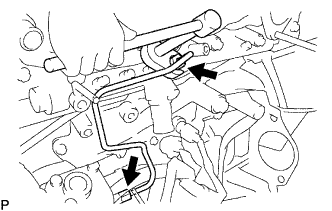
Remove the bolt and injection pipe clamp No. 2.
-
Using a union wrench 17mm, loosen the fuel inlet union of common rail side.
-
Using a union wrench 17 mm, loosen the fuel inlet pipe union of pump side.
-
Remove the inlet pipe sub-assembly.
Note
After removing the fuel pipe, affix the gum tape to the pump, common rail, and the whole injector installation area of the cylinder head cover for preventing dust.
-
-
REMOVE INSTALL INJECTION PUMP ASSEMBLY
-
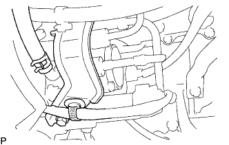
Disconnect the 2 connectors from the injection pump.
-
Remove the bolt and stay from the injection pump assembly.
-
Disconnect the fuel hose from the injection pump assembly.
-
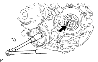
Text in Illustration *a Hold Hold the crankshaft pulley, and remove the injection pump drive gear set nut.
Note
Do not turn the crankshaft pulley. The valve heads will hit against the piston top.
-
Remove the O-ring from the injection pump drive gear.
-
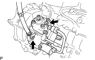
Remove the 2 nuts holding the injection pump to the timing gear case.
-
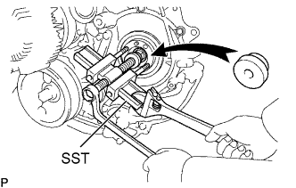
Remove the Injection Pump.
- SST
- 09950-40011 ( 09957-04010 )
- 09950-50013 ( 09951-05010, 09952-05010, 09953-05010, 09954-05021 )
Note
-
Tighten the 2 bolts more then 8 mm (0.31 in.).
-
Set SST so that it is balanced.
-
Do not hold or carry the injection pump by the adjusting lever.
-
Do not put the injection pump at an angle more than 45 from the horizontal.
-