CYLINDER HEAD GASKET INSTALLATION

-
INSTALL CYLINDER HEAD GASKET
-
Check piston protrusions for each cylinder
-
Clean the cylinder block with solvent.
-
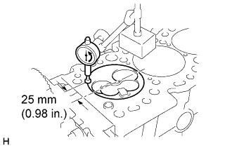
Set the piston of the cylinder to be measured to slightly before TDC.
-
Place a dial indicator on the cylinder block, set the measuring tip as shown in the illustration.
-
Set the dial indicator at 0 mm (0 in.).
Tech Tips
-
Use a dial indicator measuring tip as shown in the illustration.
-
Make sure that the measuring tip is square to the cylinder block gasket surface and piston head when taking the measurements.
-
-
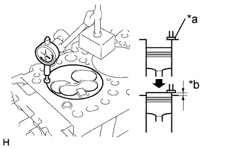
Text in Illustration *a Measuring Tip *b Protrusion Find where the piston head protrudes most by slowly turning the crankshaft clockwise and counterclockwise.
-
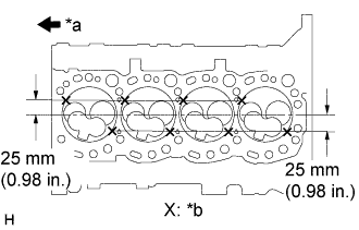
Text in Illustration *a Front *b Measuring Point Measure each cylinder at 2 places as shown in the illustration, making a total of 8 measurements.
-
For the piston protrusion value of each cylinder, use the average of the 2 measurements of each cylinder.
Protrusion 0.68 - 0.97 mm (0.00268 - 0.0382 in.) Tech Tips
When removing piston and connecting rod assembly: If the protrusion is not as specified, remove the piston and connecting rod assembly and reinstall it.
(See cylinder block disassembly and assembly)
-
-
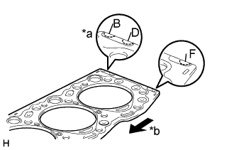
Text in Illustration *a Cutout Mark *b Front Select new cylinder head gasket
Tech Tips
There are 3 sizes of new cylinder head gaskets, marked "B", "D" or "F" accordingly.
New installed cylinder head gasket thickness Mark B 1.40 - 1.50 mm (0.0551 - 0.0591 in.) Mark D 1.50 - 1.60 mm (0.0591 - 0.0630 in.) Mark F 1.60 - 1.70 mm (0.0630 - 0.0669 in.)
-
Select the largest piston protrusion value from the measurements made, then select a new appropriate gasket according to the table below.
Piston protrusion (mm (in.)) Gasket size 0.68 - 0.77 (0.0268 - 0.0303) Use B 0.78 - 0.87 (0.0307 - 0.0343) Use D 0.88 - 0.97 (0.0346 - 0.0382) Use F
-
-
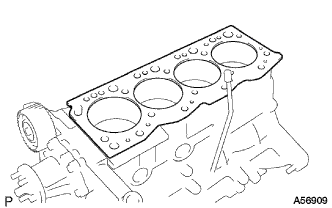
Place a new cylinder head gasket in position on the cylinder block.
Note
Be careful of the installation direction.
-
-
INSTALL CYLINDER HEAD SUB-ASSEMBLY
Tech Tips
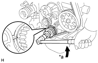
Set the No.1 cylinder to 90° BTDC/compression to avoid interference with the piston top and valve head.
Text in Illustration *a Turn
-
Using the crankshaft pulley bolt, turn the crankshaft 90° counterclockwise, and put the timing mark of the crankshaft timing pulley with the protrusion of the timing belt case.
-
Place the cylinder head in position on the cylinder head gasket.
-
Install cylinder head bolts
Tech Tips
-
The cylinder head bolts are tightened in 3 progressive steps (steps (2), (4) and (5)).
-
If any bolts is broken or deformed, replace it.
-
Apply a light coat of engine oil on the threads and under the heads of the cylinder head bolts.
-
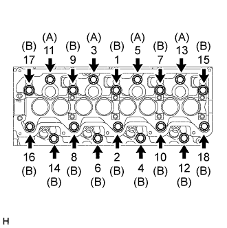
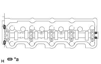
Install and uniformly tighten the 18 cylinder head bolts, in several passes, in the sequence shown.
- Torque:
- 78 N*m { 800 kgf*cm, 58 ft.*lbf }
Tech Tips
Each bolt length is indicated in the illustration.
Bolt length 107 mm (4.12 in.) for A 127 mm (5.00 in.) for B If any one of the cylinder head bolts does not meet the torque specification, replace the cylinder head bolt.
-
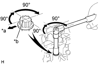
Text in Illustration *a Front *b Painted Mark Mark the front of the cylinder head bolt with paint.
-
Re-tighten the cylinder head bolts 90° in the numerical order shown.
-
Re-tighten cylinder head bolts by an additional 90°.
-
Check that the painted mark is now facing rearward.
-
-
-
INSTALL CYLINDER HEAD COVER SUB-ASSEMBLY
-
Text in Illustration *a Seal Packing Remove any old packing (FIPG) material.
-
Apply seal packing to the cylinder head as shown in the illustration.
Seal packing Toyota Genuine Seal Packing Black, Three Bond 1207B or equivalent -
Install the gasket to the cylinder head cover.
-
Install the cylinder head cover with 8 bolts and 2 nuts. Uniformly tighten the bolts and nuts in several passes.
-
-
INSTALL CYLINDER HEAD COVER NO.2 (w/ Cylinder Head Cover No.2)
-
Install the cylinder head cover silencer to the cylinder head cover.
-
Install the cylinder head cover with the 4 plate washers and nuts.
- Torque:
- 12 N*m { 120 kgf*cm, 9 ft.*lbf }
-
-
INSTALL OIL FILLER CAP SUB-ASSEMBLY
-
INSTALL INTAKE AIR CONNECTOR SUB-ASSEMBLY
-
Install a new gasket to the intake manifold.
-
Install the intake air connector with the 3 nuts and bolt.
- Torque:
- 12 N*m { 120 kgf*cm, 9 ft.*lbf }
-
-
INSTALL INJECTION PIPE SUB-ASSEMBLY NO.4
-
INSTALL INJECTION PIPE SUB-ASSEMBLY NO.3
-
INSTALL INJECTION PIPE SUB-ASSEMBLY NO.2
-
INSTALL INJECTION PIPE SUB-ASSEMBLY NO.1
-
INSTALL THROTTLE CONTROL CABLE SUPPORT
- Torque:
- 19 N*m { 195 kgf*cm, 14 ft.*lbf }
-
INSTALL EXHAUST PIPE ASSEMBLY FRONT
-
INSTALL EXHAUST FRONT PIPE ASSEMBLY NO.2
-
INSTALL EXHAUST MANIFOLD HEAT INSULATOR NO.1
-

Install the heat insulator with the 3 bolts.
- Torque:
- A
- 12 N*m { 120 kgf*cm, 9 ft.*lbf }
- B
- 19 N*m { 195 kgf*cm, 14 ft.*lbf }
-
-
INSTALL ENGINE HANGER NO.2
-
REMOVE TIMING BELT
-
INSTALL RADIATOR ASSEMBLY
-
INSTALL WATER BY-PASS HOSE NO.2 (w/ ACSD)
-
INSTALL WATER BY-PASS HOSE (w/ ACSD)
-
INSTALL HEATER WATER OUTLET HOSE A (FROM HEATER UNIT) (W/ HEATER)
-
INSTALL HEATER WATER INLET HOSE A (W/ HEATER)
-
INSTALL ENGINE UNDER COVER SUB-ASSEMBLY NO.1
-
INSTALL ENGINE SERVICE HOLE SUB COVER SUB-ASSEMBLY (W/O TILT CAB CAB TYPE)
- Torque:
- 11.5 N*m { 115 kgf*cm, 8.5 ft.*lbf }
-
INSTALL PARKING BRAKE SHOE LEVER SUB-ASSEMBLY (W/O TILT CAB CAB TYPE)
-
INSTALL TRANSMISSION FLOOR SHIFT ASSEMBLY (W/O TILT CAB CAB TYPE)
for G54 Manual Transmission
for R451 Manual Transmission
-
INSTALL FRONT SEAT ASSEMBLY (DRIVER SEAT) (W/O TILT CAB CAB TYPE)
-
Temporarily install front side of the front seat assembly RH with the 2 bolts.
-
Install the 2 rear side bolts.
- Torque:
- 39.0 N*m { 398 kgf*cm, 29 ft.*lbf }
-
Tighten the 2 front side bolts.
- Torque:
- 39.0 N*m { 398 kgf*cm, 29 ft.*lbf }
-
Install the seat track cover.
-
-
CHECK ENGINE COOLANT LEAK
-
REFILL ENGINE COOLANT
-
BLEED INJECTION PIPE
-
Move the priming pump in the upper part of the fuel filter assembly up and down, and fill the injection pump assembly and fuel system with fuel.
-
Loosen one of the flare nuts (in the nozzle side).
-
Crank the engine until fuel comes out from the flare nut (in the nozzle side).
-
Tighten the flare nut.
- Torque:
- 24.5 N*m { 250 kgf*cm, 18 ft.*lbf }
-
The above operations should be carried out in each injection pipe.
-
-
CHECK FUEL LEAK