TIMING BELT INSTALLATION

-
INSTALL TIMING BELT
-
Remove any oil or water on each pulleys, and keep them clean.
-
Install the timing belt on the crankshaft timing and No. 1 idler pulleys.
-
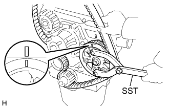
Using SST, slightly turn the injection pump drive pulley clockwise. Hang the timing belt on the drive pulley, and align the timing marks of the drive pulley and timing belt case.
- SST
- 09960-10010 ( 09962-01000, 09963-01000 )
-
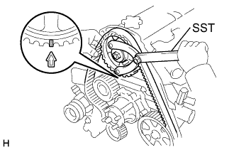
Using SST, Slightly turn the camshaft timing pulley clockwise. Hang the timing belt on the timing pulley, and align the timing marks of the timing pulley and timing belt case.
- SST
- 09960-10010 ( 09962-01000, 09963-01000 )
-
Check that the timing belt has tension between the injection pump drive and camshaft timing pulleys.
-
Install the timing belt on the No. 2 idler pulley.
-
-
CHECK VALVE TIMING
-
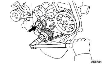
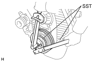
Loosen the No. 1 idler pulley bolt (A), and stretch the timing belt.
-
Slowly the crankshaft pulley 2 revolutions from TDC to TDC.
Note
Always turn the crankshaft clockwise.
-
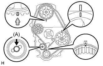
Check that each pulley aligns with the timing marks as shown in the illustration.
If the timing marks do not align, remove the timing belt and reinstall it.
-
Tighten the No. 1 idler pulley bolt (A).
- Torque:
- 44 N*m { 450 kgf*cm, 33 ft.*lbf }
-
-
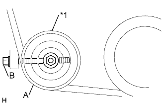
INSTALL TIMING BELT GUIDE
-
Text in Illustration *1 Collar Install the belt guide, facing the cup side outward.
-
-
INSTALL TIMING CHAIN OR BELT COVER SUB-ASSEMBLY
-
Install the collar to the timing pointer.
-
Install the 2 gaskets to the timing belt cover.
-
Install the timing belt cover with the 11 bolts.
-
-
INSTALL CRANKSHAFT PULLEY
-
Align the pulley set key with the key groove of the pulley, and slide the pulley to the crankshaft.
-
Using SST, install the new pulley bolt.
- Torque:
- 235 N*m { 2400 kgf*cm, 173 ft.*lbf }
-
-
INSTALL VANE PUMP DRIVE PULLEY
-
Install the vane pump drive pulley and vane pump pulley spacer with the 4 bolts.
- Torque:
- 19 N*m { 195 kgf*cm, 14 ft.*lbf }
-
w/ A/C
Install the vane pump drive pulley and crankshaft pulley No.2 with the 4 bolts.
- Torque:
- 19 N*m { 195 kgf*cm, 14 ft.*lbf }
-
-
INSTALL COMPRESSOR MOUNTING BRACKET NO.1 (W/ AIR CONDITIONER)
- Torque:
- 85.6 N*m { 876 kgf*cm, 63 ft.*lbf }
-
INSTALL COMPRESSOR AND MAGNETIC CLUTCH (W/ AIR CONDITIONER)
- Torque:
- 24.5 N*m { 250 kgf*cm, 18 ft.*lbf }
-
INSTALL FAN AND GENERATOR V BELT
-
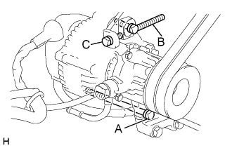
For vehicles with A/C.
-
Install the V belt.
-
Tightening the bolt C, adjust the tension of the V belt.
-
Tighten the bolts A and B.
- Torque:
- Bolt A
- 65 N*m { 650 kgf*cm, 48 ft.*lbf }
- Bolt B
- 18 N*m { 185 kgf*cm, 13 ft.*lbf }
-
Check the tension of the V belt Click here.
-
-
For vehicles without A/C.
-
Install the V belt.
-
Using a bar, adjust the tension of the V belt.
-
Tighten the bolts A and B.
-
Check the tension of the V belt.
- Torque:
- Bolt A
- 65 N*m { 650 kgf*cm, 48 ft.*lbf }
- Bolt B
- 18 N*m { 185 kgf*cm, 13 ft.*lbf }
-
Check the tension of the V belt Click here.
-
-
-
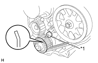
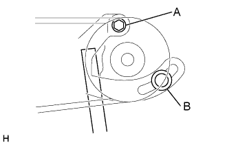
INSTALL V (COOLER COMPRESSOR TO CRANKSHAFT PULLEY) BELT NO.1
-
Text in Illustration *1 Idler pulley Install the V belt.
-
Tightening the bolt B, adjust the tension of the V belt.
-
Tighten nut A.
- Torque:
- 39 N*m { 400 kgf*cm, 29 ft.*lbf }
-
Check the tension of the V belt Click here.
-
-
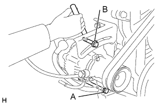
INSTALL VANE PUMP V BELT
-
Install the V belt.
-
Using a bar, adjust the tension of the V-ribbed belt.
-
Tighten the bolts A and B.
- Torque:
- Bolt A
- 72 N*m { 730 kgf*cm, 53 ft.*lbf }
- Bolt B
- 48 N*m { 490 kgf*cm, 35 ft.*lbf }
-
Check the tension of the V belt Click here.
-
-
INSTALL RADIATOR ASSEMBLY
-
INSTALL ENGINE UNDER COVER SUB-ASSEMBLY NO.1
-
INSTALL ENGINE SERVICE HOLE SUB COVER SUB-ASSEMBLY (W/O TILT CAB CAB TYPE)
- Torque:
- 11.5 N*m { 115 kgf*cm, 8.5 ft.*lbf }
-
INSTALL PARKING BRAKE SHOE LEVER SUB-ASSEMBLY (W/O TILT CAB CAB TYPE)
-
INSTALL TRANSMISSION FLOOR SHIFT ASSEMBLY (W/O TILT CAB CAB TYPE)
G54 Manual Transmission
R451 Manual Transmission
-
INSTALL FRONT SEAT ASSEMBLY (DRIVER SEAT) (W/O TILT CAB CAB TYPE)
-
Temporarily install front side of the front seat assembly RH with the 2 bolts.
-
Install the 2 rear side bolts.
- Torque:
- 39.0 N*m { 398 kgf*cm, 29 ft.*lbf }
-
Tighten the 2 front side bolts.
- Torque:
- 39.0 N*m { 398 kgf*cm, 29 ft.*lbf }
-
Install the seat track cover.
-
-
REFILL ENGINE COOLANT
-
CHECK ENGINE COOLANT LEAK