ENGINE ON-VEHICLE INSPECTION

-
INSPECT COOLANT
-
INSPECT ENGINE OIL
-
INSPECT BATTERY SPECIFIC GRAVITY
-
INSPECT AIR CLEANER FILTER ELEMENT SUB-ASSEMBLY
-
INSPECT VANE PUMP V BELT
-
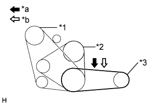
Text in Illustration *1 Compressor *2 Fan pulley *3 Vane pump *a Measure Point for Belt Looseness *b Measure Point for Belt Tension Check the V belt deflection.
-
Belt deflection
Pressing force 98 N (10 kgf, 22lbf) New belt
mm (in.)
Used belt
mm (in.)
V belt 8.0 - 10.0
(0.31 - 0.39)
10.0 - 14.0
(0.39 - 0.55)
V - ribbed belt 6.0 - 8.0
(0.24 - 0.31)
8.0 - 12.0
(0.31 - 0.47)
-
Tension
New belt
N (kgf)
Used belt
N (kgf)
V belt 440 - 540
(45 - 55)
195 - 345
(20 - 35)
V - ribbed belt 540 - 400
(55 - 65)
245 - 395
(25 - 40)
Note
-
Check the drive belt deflection at the specified point.
-
When installing a new belt, set its tension value as specified.
-
When checking a belt used for over 5 minutes, confirm the deflection value is within the specified one.
-
When reinstalling a belt used for over 5 minutes, perform the check based on the used deflection value.
-
V belt tension and deflection value should be checked after two revolution of engine cranking.
-
When using a belt tension gauge, confirm the accuracy first by using a master gauge.
-
-
-
-
INSPECT V (COOLER COMPRESSOR TO CRANKSHAFT PULLEY) BELT NO.1
-
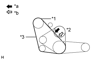
Text in Illustration *1 Compressor *2 Fan pulley *3 Alternator *a Measure Point for Belt Looseness *b Measure Point for Belt Tension Check the V belt deflection.
-
Belt deflection
Pressing force 98 N (10 kgf, 22 lbf) New belt
mm (in.)
Used belt
mm (in.)
10 - 14
(0.39 - 0.56)
14 - 20
(0.55 - 0.79)
-
Tension
New belt
N (kgf)
Used belt
N (kgf)
372 - 608
(38 - 62)
196 - 392
(20 - 40)
Note
-
Check the drive belt deflection at the specified point.
-
When installing a new belt, set its tension value as specified.
-
When checking a belt used for over 5 minutes, confirm the deflection value is within the specified one.
-
When reinstalling a belt used for over 5 minutes, perform the check based on the used deflection value.
-
V belt tension and deflection value should be checked after two revolution of engine cranking.
-
When using a belt tension gauge, confirm the accuracy first by using a master gauge.
-
-
-
-
INSPECT FAN AND GENERATOR V BELT
-
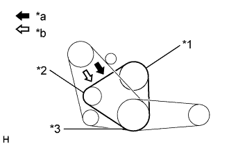
Text in Illustration *1 Fan pulley *2 Alternator *3 Crank Shaft *a Measure Point for Belt Looseness *b Measure Point for Belt Tension Check the V belt deflection. (Per 1 belt)
-
Belt deflection
Pressing force 98 N (10 kgf, 22 lbf) New belt
mm (in.)
Used belt
mm (in.)
7.0 - 10
(0.28 - 0.39)
10 - 14
(0.39 - 0.56)
-
Tension. (Per 1 belt)
New belt
mm (in.)
Used belt
mm (in.)
430 - 540
(44 - 55)
195 - 345
(20 - 35)
Note
-
Check the drive belt deflection at the specified point.
-
When installing a new belt, set its tension value as specified.
-
When checking a belt used for over 5 minutes, confirm the deflection value is within the specified one.
-
When reinstalling a belt used for over 5 minutes, perform the check based on the used deflection value.
-
V belt tension and deflection value should be checked after two revolution of engine cranking.
-
When using a belt tension gauge, confirm the accuracy first by using a master gauge.
-
-
-
-
INSPECT INJECTION TIMING
Tech Tips
Inspect and adjust the injection timing when the engine cold.
-
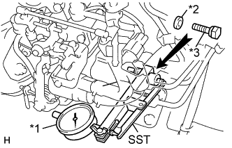
Text in Illustration *1 Dial Indicator *2 Gasket *3 Plug Bolt Remove the plug bolt and gasket from the distributive head plug of the injection pump.
-
Install SST (plunger stroke measuring tool) and a dial indicator to the plug bolt hole of distributive head plug.
- SST
- 09275-54011
-
Text in Illustration *1 Metal Plate *a Turn Using a screwdriver, turn the cold starting lever counterclockwise approx. 20°.
-
Put a metal plate (thickness of 8.5 - 10.0 mm (0.335 - 0.394 in.)) between the cold starting lever and thermo wax plunger.
-
Turn the crankshaft pulley clockwise so the pulley groove is 25 - 30° from the timing pointer.
Note
Do not turn the crankshaft pulley counterclockwise.
-
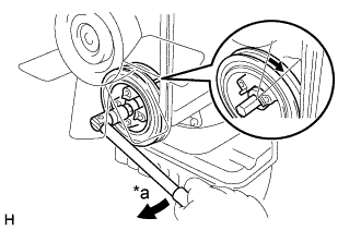
Text in Illustration *a Turn Set the dial indicator at 0 mm (0 in.).
-
Slowly rotate the crankshaft pulley clockwise until its groove is aligned with the timing pointer.
-
Measure the plunger stroke.
Plunger stroke w/ TCV 0.47 - 0.53 mm (0.0185 - 0.0209 in.) w/o TCV 0.67 - 0.73 mm (0.0265 - 0.0287 in.)
-
-
ADJUST INJECTION TIMING
-
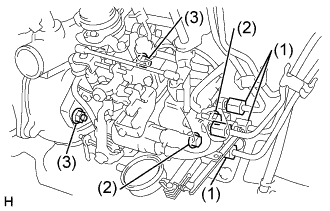
Loosen these nuts and bolts:
-
4 union nuts holding injection pipes to injection pump
-
2 bolts holding injection pump to injection pump stay
-
2 nuts holding injection pump to timing belt case
Note
Do not turn the nuts more than 90°.
-
-
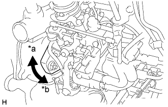
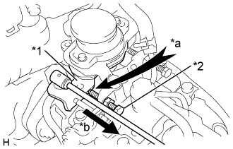
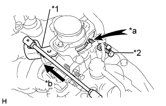
Text in Illustration *a Greater than Specification *b Less than Specification Adjust plunger stroke by slightly tilting the injection pump body.
If the stroke is less than specification, tilt the pump toward the engine.
If the stroke is greater than specification, tilt the pump away from the engine.
-
Tighten these nuts and bolts:
-
2 nuts holding injection pump to timing belt case
- Torque:
- 20.5 N*m { 210 kgf*cm, 15 ft.*lbf }
-
2 bolts holding injection pump to injection pump stay
- Torque:
- 18 N*m { 185 kgf*cm, 13 ft.*lbf }
-
4 nuts holding injection pipes to injection pump
- Torque:
- 24.5 N*m { 250 kgf*cm, 18 ft.*lbf }
-
-
Recheck the plunger stroke.
-
Remove SST and dial indicator.
-
Remove the metal plate.
-
Install a new gasket and the plug bolt of the distributive head plug.
- Torque:
- 17 N*m { 170 kgf*cm, 12 ft.*lbf }
-
Start engine and check for fuel leaks.
-
-
INSPECT INJECTION PRESSURE TEST
-
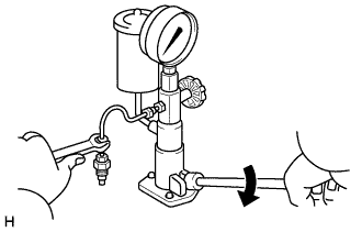
Install the injection nozzle to the injection nozzle hand tester and bleed air from the union nut.
CAUTION:
Do not place your finger over the nozzle injection hole.
-
Pump the tester handle a few times as fast as possible to discharge the carbon from the injection hole.
-
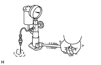
Pump the tester handle slowly and observe the pressure gauge.
-
Read the pressure gauge just as the injection pressure begins to drop.
Opening pressure (New nozzle) 15790 - 16570 kPa (159 - 171 kgf*cm2, 2129 - 2404 psi) Opening pressure (Reused nozzle) 15200 - 16181 kPa (154 - 166 kgf*cm2, 2205 - 2347 psi) Tech Tips
Proper nozzle operation can be determined by a swishing sound.
If the opening pressure in not as specified, disassemble the nozzle holder and change the adjusting shim on the top of the pressure spring.
Adjusted opening pressure 15200 - 16181 kPa (154 - 166 kgf*cm2, 2205 - 2347 psi) Adjusting shim thickness (mm (in.)) 0.900 (0.0354) 1.300 (0.0512) 1.700 (0.0669) 0.950 (0.0374) 1.350 (0.0531) 1.750 (0.0689) 1.000 (0.0394) 1.400 (0.0551) 1.800 (0.0709) 1.050 (0.0413) 1.450 (0.0571) 1.850 (0.0728) 1.100 (0.0433) 1.500 (0.0591) 1.900 (0.0748) 1.150 (0.0453) 1.550 (0.0610) 1.950 (0.0768) 1.200 (0.0472) 1.600 (0.0630) - 1.250 (0.0492) 1.650 (0.0650) - Tech Tips
-
Varying the adjusting shim thickness by 0.05 mm (0.0020 in.) changes the injection pressure by about 628 kPa (6.4 kgf*cm2, 91 psi).
-
Only one adjusting shim should be used.
-
After adjustment, adjust the accelerator linkage.
-
-
-
INSPECT AND ADJUST IDLE SPEED
-
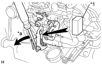
Text in Illustration *1 Adjusting Lever *2 Idle Speed Screw *a Touch *b Release Connect the tachometer.
-
Warm up engine.
-
Check that the adjusting lever touches the idle speed adjusting screw when the accelerator pedal is released.
If not, adjust the accelerator linkage.
-
Start the engine.
-
Check the idle speed.
Idle speed 650 - 750 rpm -
Adjust the idle speed.
-
Disconnect the accelerator linkage.
-
Loosen the lock nut of the idle speed adjusting screw.
-
Adjust the idle speed by turning the idle speed adjusting screw.
-
Securely tighten the lock nut, and recheck the idle speed.
-
Reconnect the accelerator linkage.
-
-
-
INSPECT AND ADJUST MAXIMUM SPEED
-
Text in Illustration *1 Adjusting Lever *2 Maximum Speed Adjusting Screw *a Touch *b Depress Check that the adjusting lever touches the maximum speed adjusting screw when the accelerator pedal is depressed all the way.
If not, adjust the accelerator linkage.
-
Start the engine.
-
Depress the accelerator pedal all the way.
-
Check the maximum speed.
Maximum speed w/ TCV 4670 - 4930 rpm w/o TCV 4770 - 5030 rpm -
Adjust the maximum speed.
-
Disconnect the accelerator linkage.
-
Cut off the seal wire of the maximum speed adjusting screw.
-
Loosen the lock nut of the maximum speed adjusting screw.
-
Adjust the maximum speed by turning the maximum speed adjusting screw.
Tech Tips
Adjust at idle speed. Then, raise engine speed and recheck the maximum speed.
-
Text in Illustration *1 Seal Wire Securely tighten the lock nut.
-
Recheck the maximum speed.
-
Reconnect the accelerator linkage.
-
After adjustment, adjust the accelerator linkage.
-
Seal the maximum speed adjusting screw with a new seal wire.
-
-
-
INSPECT COMPRESSION
Tech Tips
If there is lack of power, excessive oil consumption or poor fuel economy, measure the compression pressure.
-
Warm up and stop engine.
-
Remove the glow plugs.
-
Disconnect injection pump (fuel cut solenoid) connector.
-
Check cylinder compression pressure.
Tech Tips
Turn the starter before measuring the compression and discharge the foreign objects.
-
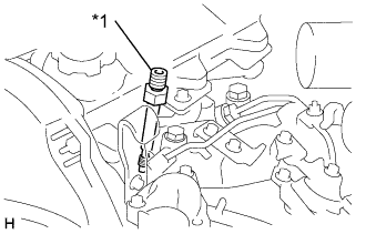
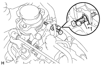
Text in Illustration *1 SST (Attachment) Install SST (attachment) to the glow plug hole.
- Torque:
- 13 N*m { 130 kgf*cm, 9 ft.*lbf }
-
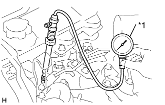
Text in Illustration *1 SST (Compression Gauge) Connect SST (compression gauge) to the SST (attachment).
- SST
- 09992-00026 ( 09992-00211 )
-
Fully open the throttle valve, and start the engine.
-
While cranking the engine, measure the compression pressure.
Tech Tips
Always use a fully charged battery to obtain engine revolution of 250 rpm or more.
-
Repeat steps (a) through (d) for each cylinder.
Note
This measurement must be done in as short a time as possible.
Compression pressure 3138 kPa (32.0 kgf*cm2, 455 psi) or more Minimum pressure 1961 kPa (20.0 kgf*cm2, 284 psi) Difference between each cylinder 490 kPa (5.0 kgf*cm2, 71 psi) or less -
If the cylinder compression in one or more cylinders is low, pour a small amount of engine oil into the cylinder through the glow plug hole and repeat steps (a) through (d) for the cylinder with low compression.
-
If adding oil helps the compression, chances are that the piston rings and/or cylinder bore are worn or damaged.
-
If pressure stays low, a valve may be sticking or seating improperly, or there may be leakage past the gasket.
-
-
Remove the SST.
-
Reinstall the glow plugs.
-
Reconnect injection pump (fuel cut solenoid) connector.
-
-
INSPECT DIESEL SMOKE