ENGINE UNIT REASSEMBLY

-
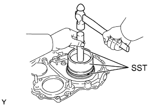
INSTALL INJECTION GEAR BEARING
-
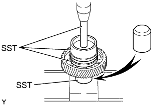
Using SST and a press, press in a new bearing.
- SST
- 09223-00010
- 09223-15020
- 09502-12010
- 09950-70010 ( 09951-07100 )
-
-
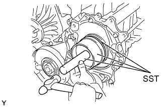
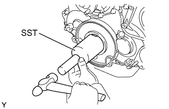
INSTALL ENGINE REAR OIL SEAL
-
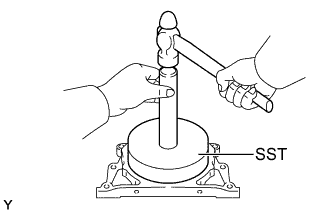
Using SST and a hammer, tap in a new oil seal until its surface is flush with the rear oil seal retainer edge.
- SST
- 09223-15030
- 09950-70010 ( 09951-07100 )
-
Apply MP grease to the oil seal lip.
-
-
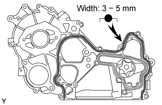
INSTALL ENGINE REAR OIL SEAL RETAINER
-
Remove any old packing (FIPG) material and be careful not to drop any oil on the contact surfaces of the retainer and cylinder block.
-
Using a razor blade and gasket scraper, remove all the old packing (FIPG) material from the gasket surfaces and sealing groove.
-
Thoroughly clean all components to remove all the loose material.
-
Using a non-residue solvent, clean both sealing surfaces.
-
-

Apply seal packing to the retainer as shown in the illustration.
Seal packing Toyota Genuine Seal Packing Black, Three Bond 1207B or equivalent
-
Install a nozzle that has been cut to a 3 - 5mm(0.12 - 0.20 in.) opening.
Tech Tips
Avoid applying an excessive amount to the surface.
-
Parts must be assembled within 5 minutes of application. Otherwise the material must be removed and reapplied.
-
Immediately remove nozzle from the tube and reinstall cap.
-
-
Install the retainer with the 5 bolts.
- Torque:
- 13 N*m { 133 kgf*cm, 10 ft.*lbf }
-
-
INSTALL TIMING GEAR CASE ASSEMBLY
-
Remove any old packing (FIPG) material and be careful not to drop any oil on the contact surfaces of the timing gear case and cylinder block.
-
Using a razor blade and gasket scraper, remove all the old packing (FIPG) material from the gasket surfaces and sealing groove.
-
Thoroughly clean all components to remove all the loose material.
-
Using a non-residue solvent, clean both sealing surfaces.
-
-
Insert the driven rotor into the timing gear case Click here.
-
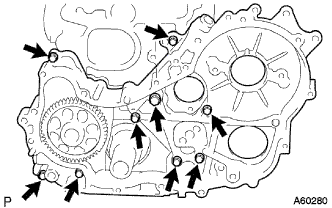
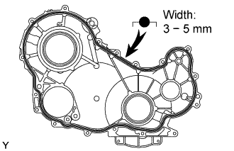
Apply seal packing to the timing gear case as shown in the illustration.
Seal packing Toyota Genuine Seal Packing Black, Three Bond 1207B or equivalent
-
Install a nozzle that has been cut to a 3 - 5mm(0.16 - 0.20 in.) opening.
Tech Tips
Avoid applying an excessive amount to the surface.
-
Parts must be assembled within 5 minutes of application. Otherwise the material must be removed and reapplied.
-
Immediately remove nozzle from the tube and reinstall cap.
-
-
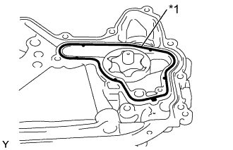
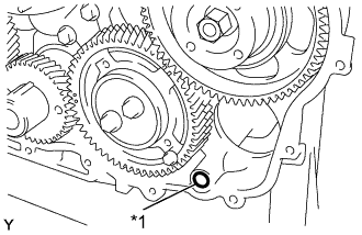
Text in Illustration *1 New Gasket Install a new gasket to the groove of the timing gear case.
-
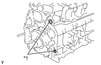
Text in Illustration *1 New O-ring Install 2 new O-rings to the cylinder block groove of the timing gear case.
-
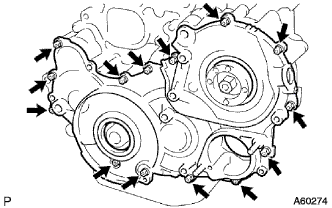
Install the timing gear case with the union bolt and 8 bolts.
- Torque:
- for Union nut
- 13 N*m { 133 kgf*cm, 10 ft.*lbf }
- for Bolt
- 16 N*m { 163 kgf*cm, 12 ft.*lbf }
-
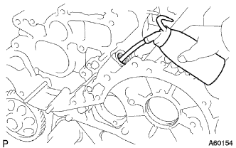
Remove the screw plug.
-
Pour in approx. 20 cc (0.12 cu in.) of engine oil into the oil pump.
-
Reinstall a new gasket and the screw plug.
- Torque:
- 41.5 N*m { 423 kgf*cm, 31 ft.*lbf }
-
-
INSTALL OIL STRAINER SUB-ASSEMBLY
-
Install a new gasket and the oil strainer with the 2 bolts and 2 nuts.
- Torque:
- 8.0 N*m { 82 kgf*cm, 71 in.*lbf }
-
-
INSTALL OIL PAN SUB-ASSEMBLY
-
Remove any old packing (FIPG) material and be careful not to drop any oil on the contact surfaces of the oil pan and cylinder block.
-
Using a razor blade and gasket scraper, remove all the old packing (FIPG) material from the gasket surfaces and sealing groove.
-
Thoroughly clean all components to remove all the loose material.
-
Using a non-residue solvent, clean both sealing surfaces.
Note
Do not use a solvent which will affect the painted surfaces.
-
-
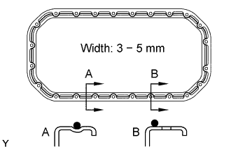
Apply seal packing to the oil pan as shown in the illustration.
Seal packing Toyota Genuine Seal Packing Black, Three Bond 1207B or equivalent
-
Install a nozzle that has been cut to a 3 - 5mm(0.12 - 0.20 in.) opening.
-
Parts must be assembled within 5 minutes of application. Otherwise the material must be removed and reapplied.
-
Immediately remove nozzle from the tube and reinstall cap.
-
-
Install the oil pan with the 22 bolts and 2 nuts.
- Torque:
- 16 N*m { 163 kgf*cm, 12 ft.*lbf }
-
-
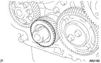
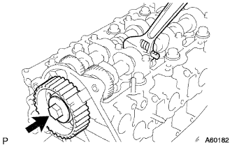
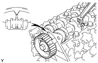
INSTALL CRANKSHAFT TIMING GEAR OR SPROCKET
-
Face the crankshaft timing gear with timing mark 1 facing the forward.
-
Align the set key on the crankshaft with the key groove of the crankshaft timing gear.
-
Using SST and a hammer, tap in the timing gear.
- SST
- 09223-00010
-
-
INSTALL INJECTION GEAR
-
Install the supply pump with the 2 nuts.
- Torque:
- 21 N*m { 214 kgf*cm, 15 ft.*lbf }
-
Temporarily install the supply pump drive gear with the nut.
-
-
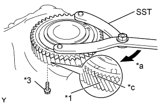
INSTALL IDLE SUB GEAR NO.2
-
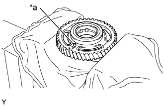
Text in Illustration *a Pin Mount the idler gear in a vise as shown in the illustration.
Note
Be careful not to damage the gear.
-
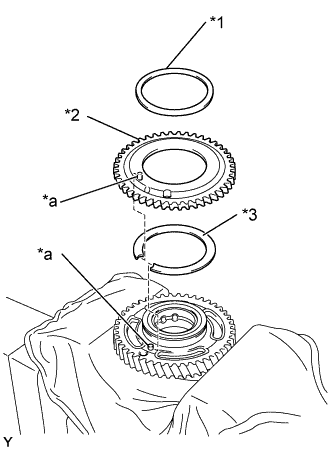
Text in Illustration *1 Wave Washer *2 Sub Gear *3 Gear Spring *a Pin Install the gear spring.
-
Install the sub gear.
Tech Tips
Align the pins on the gears with the spring ends.
-
Install the wave washer.
-
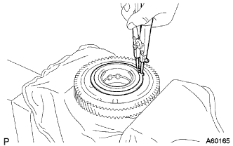
Using snap ring pliers, install the snap ring.
-
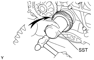
Text in Illustration *1 Main Gear *2 Sub Gear *3 Service Bolt *a Turn Using SST, align the holes of the idler gear and sub gear by turning the sub gear clockwise, and install a service bolt.
Recommended service bolt Thread diameter 6 mm Thread pitch 1.0 mm Bolt length Approx. 19 mm (0.75 in.) - SST
- 09960-10010 ( 09962-01000, 09963-00700 )
-
Align the gear teeth of the main gear sub gear, and tighten the service bolt.
-
-
INSTALL IDLE GEAR NO.1
-
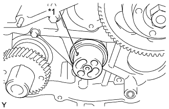
Text in Illustration *1 Oil Hole Install the gear shaft as shown in the illustration.
-
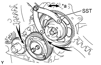
Text in Illustration *a Turn Align timing marks 5 of the idle gear and crankshaft timing gear
-
Using SST, turn the injection gear, and align timing marks 4 of the idle gear and injection gear, and mesh the gears.
- SST
- 09960-10010 ( 09962-01000, 09963-01000 )
-
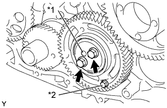
Text in Illustration *1 Protrusion *2 Service Bolt Face the thrust plate with the protrusion facing the forward.
-
Align the bolt holes, and Install the thrust plate with the 2 bolts.
- Torque:
- 50 N*m { 510 kgf*cm, 37 ft.*lbf }
-
Remove the service bolt.
-
-
INSTALL CRANKSHAFT POSITION SENSOR PLATE NO.1
-
Align the set key with the key groove of the sensor plate.
-
Install the sensor plate, facing the cup side outward.
-
-
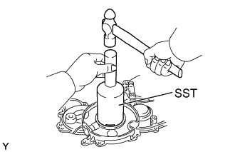
INSTALL TIMING GEAR COVER OIL SEAL (for Injection Gear)
Tech Tips
there are 2 methods ((a) and (b)) to remove the oil seal.
-
If the timing gear cover is removed from cylinder block:
-
Using SST and a hammer, tap in a new oil seal until its surface is flush with the timing gear cover edge.
- SST
- 09223-15020
- 09502-12010
- 09950-70010 ( 09951-07100 )
-
Apply MP grease to the oil seal lip.
-
-
If the timing gear cover is installed to the cylinder block:
-
Apply MP grease to the oil seal lip.
-
Using SST and a hammer, tap in a new oil seal until its surface is flush with the timing gear cover edge.
- SST
- 09223-15020
- 09502-12010
- 09950-70010 ( 09951-07100 )
-
-
-
INSTALL TIMING GEAR COVER OIL SEAL (for Crankshaft Front)
Tech Tips
there are 2 methods ((a) and (b)) to remove the oil seal.
-
If the timing gear cover is removed from the cylinder block:
-
Using SST and a hammer, tap in a new oil seal until its surface is flush with the timing gear cover edge.
- SST
- 09214-76011
-
Apply MP grease to the oil seal lip.
-
-
If the timing gear cover is installed to the cylinder block:
-
Apply MP grease to a new oil seal lip.
-
Using SST and a hammer, tap in the oil seal until its surface is flush with the timing gear cover edge.
- SST
- 09214-76011
-
-
-
INSTALL TIMING GEAR COVER
-
Remove any old packing (FIPG) material and be careful not to drop any oil on the contact surfaces of the timing gear cover and cylinder block.
-
Using a razor blade and gasket scraper, remove all the old packing (FIPG) material from the gasket surfaces and sealing groove.
-
Thoroughly clean all components to remove all the loose material.
-
Using a non-residue solvent, clean both sealing surfaces.
-
-
Apply seal packing to the timing gear cover as shown in the illustration.
Seal packing Toyota Genuine Seal Packing Black, Three Bond 1207B or equivalent
-
Install a nozzle that has been cut to a 3 - 5mm(0.12 - 0.20 in.) opening.
-
Parts must be assembled within 5 minutes of application. Otherwise the material must be removed and reapplied.
-
Immediately remove nozzle from the tube and reinstall cap.
-
-
Text in Illustration *1 New O-ring Install a new O-ring to the timing gear case.
-
Install the timing gear cover with the 14 bolts and 2 nuts.
- Torque:
- 13 N*m { 133 kgf*cm, 10 ft.*lbf }
-
-
INSTALL WATER PUMP ASSEMBLY
-
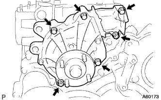
Install a new gasket and the water pump with the 5 bolts and 2 nuts.
- Torque:
- 13 N*m { 133 kgf*cm, 10 ft.*lbf }
-
-
INSTALL CYLINDER HEAD SUB-ASSEMBLY
-
Check the piston protrusions for each cylinder
-
Clean the cylinder block with solvent.
-
Set the piston of the cylinder to be measured to slightly before TDC.
-
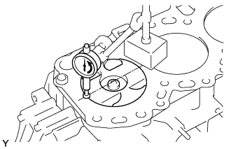
Place a dial indicator on the cylinder block, set the measuring tip as shown in the illustration.
-
Set the dial indicator at 0 mm (0 in.).
Tech Tips
-
Use a dial indicator measuring tip as shown in the illustration.
-
Make sure that the measuring tip is square to the cylinder block gasket surface and piston head when taking the measurements.
-
-
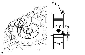
Text in Illustration *a Measuring Tip *b Protrusion Find where the piston head protrudes most by slowly turning the crankshaft clockwise and counterclockwise.
-
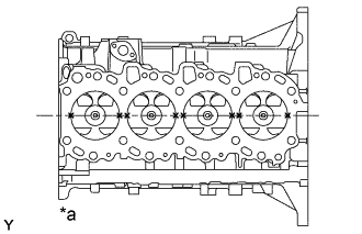
Text in Illustration *a Measuring Point Measure each cylinder at 2 places as shown in the illustration, making a total of 8 measurements.
-
For the piston protrusion value of each cylinder, use the average of the 2 measurements of each cylinder.
Piston protrusion 0.005 - 0.254 mm (0.0002 - 0.0100 in.) Tech Tips
When removing piston and connecting rod assembly:
If the protrusion is not as specified, remove the piston and connecting rod assembly and reinstall it Click here.
-
-
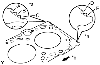
Text in Illustration *a Cutout Mark *b Front Select a new cylinder head gasket.
Tech Tips
There are 5 sizes of new cylinder head gaskets, marked A, B, C, D or E accordingly.
New installed cylinder head gasket thickness A 0.80 - 0.90 mm (0.0315 - 0.0354 in.) B 0.85 - 0.95 mm (0.0335 - 0.0374 in.) C 0.90 - 1.00 mm (0.0354 - 0.0394 in.) D 0.95 - 1.05 mm (0.0374 - 0.0413 in.) E 1.00 - 1.10 mm (0.0394 - 0.0433 in.)
-
Select the largest piston protrusion value from the measurements made, then select a new appropriate gasket according to the table below.
Piston protrusion Gasket size 0.005 - 0.054 mm (0.0002 - 0.0021 in.) Use A 0.055 - 0.104 mm (0.0022 - 0.0041 in.) Use B 0.105 - 0.154 mm (0.0041 - 0.0061 in.) Use C 0.155 - 0.204 mm (0.0061 - 0.0080 in.) Use D 0.205 - 0.255 mm (0.0081 - 0.0100 in.) Use E
-
-
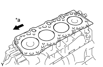
Text in Illustration *a Front Place the cylinder head on the cylinder block.
-
Place the cylinder head gasket in position on the cylinder block.
Tech Tips
Be careful of the installation direction.
-
Place the cylinder head in position on the cylinder head gasket.
-
-
Install the cylinder head bolts.
Tech Tips
-
The cylinder head bolts are tightened in 3 progressive steps (steps (2), (4) and (5)).
-
If any bolts is broken or deformed, replace it.
-
Apply a light coat of engine oil on the threads and under the heads of the cylinder head bolts.
-
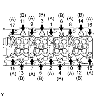
Install and uniformly tighten the 18 cylinder head bolts, in several passes, in the sequence shown.
- Torque:
- 85 N*m { 867 kgf*cm, 63 ft.*lbf }
Tech Tips
Each bolt length is indicated in the illustration.
Bolt length:
110 mm (4.33 in.) for A
167 mm (6.57 in.) for B
f any one of the cylinder head bolts does not meet the torque specification, replace the cylinder head bolt.
-
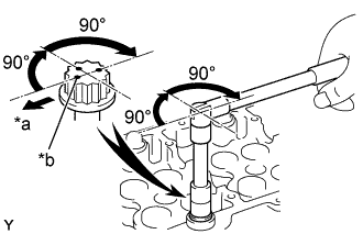
Text in Illustration *a Front *b Painted Mark Mark the front of the cylinder head bolt with paint.
-
Retighten the cylinder head bolts 90° in the numerical order shown.
-
Retighten cylinder head bolts by an additional 90°.
-
Check that the painted mark is now facing rearward.
-
-
-
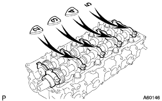
INSTALL CAMSHAFT
-
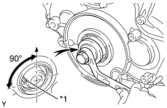
Text in Illustration *1 Set Key Using the crankshaft pulley bolt, set the No. 1 cylinder to 90° BTDC/compression.
Tech Tips
Set the No. 1 cylinder to 90° BTDC/compression to avoid interference with the piston top and valve head.
-
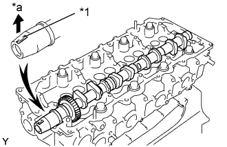
Install the camshaft.
-
Apply MP grease to the thrust portion of the camshafts.
Text in Illustration *1 Key Groove *a Upward -
Place the camshaft on the cylinder head, facing the key groove upward.
-
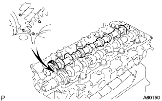
Align the timing marks (1 dot mark) of the camshaft drive and driven main gears, and place the No. 2 camshaft.
-
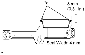
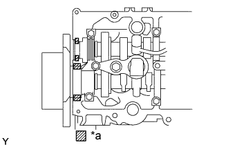
Text in Illustration *a Seal Packing Apply seal packing to the No. 1 bearing cap.
-
Remove any old packing (FIPG) material and be careful not to drop any oil on the contact surfaces of the bearing cap and cylinder head.
Using a razor blade and gasket scraper, remove all the old packing (FIPG) material from the gasket surfaces and groove.
Thoroughly clean all components to remove all the loose material.
Using a non-residue solvent, clean both sealing surfaces.
-
Apply seal packing to the bearing cap as shown in the illustration.
Install a nozzle that has been cut to a 4 mm (0.16 in.) opening.
Parts must be assembled within 5 minutes of application. Otherwise the material must be removed and reapplied.
Immediately remove nozzle from the tube and reinstall cap.
Seal packing Toyota Genuine Seal Packing Black, Three Bond 1207B or equivalent Note
Do not apply seal packing to the front bearing cap grooves.
-
-
Install the 5 bearing caps in their proper locations.
-
Apply a light coat of engine oil on the threads and under the heads of the bearing cap bolts.
-
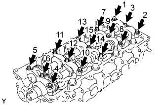
Install and uniformly tighten the 10 bearing cap bolts, in several passes, in the sequence shown.
- Torque:
- 19 N*m { 194 kgf*cm, 14 ft.*lbf }
-
-
Install the camshaft oil seal.
-
Apply MP grease to a new oil seal lip.
-
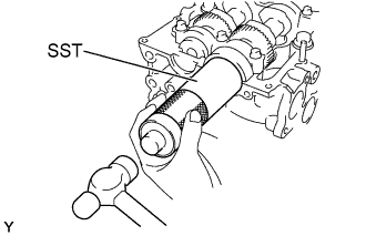
Using SST and a hammer, tap in the oil seal until its surface is flush with the oil seal retainer edge.
- SST
- 09608-06041
-
-
-
INSTALL TIMING BELT NO. 2 COVER
-
Remove any old packing (FIPG) material and be careful not to drop any oil on the contact surfaces of timing gear cover and timing belt No. 2 cover.
-
Using a razor blade and gasket scraper, remove all the old packing (FIPG) material from the gasket surfaces and sealing groove.
-
Thoroughly clean all components to remove all the loose material.
-
3) Using a non-residue solvent, clean both sealing surfaces.
-
-
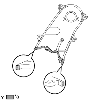
Text in Illustration *a Seal Packing Apply seal packing to the timing gear cover as shown in the illustration.
Seal packing Toyota Genuine Seal Packing Black, Three Bond 1207B or equivalent
-
Parts must be assembled within 5 minutes of application. Otherwise the material must be removed and reapplied.
-
Immediately remove nozzle from the tube and reinstall cap.
-
-
Install the timing belt No. 2 cover with the 4 bolts and nut.
- Torque:
- 10 N*m { 102 kgf*cm, 7 ft.*lbf }
-
-
INSTALL CAMSHAFT TIMING PULLEY
-
Install the set key to the key groove of the camshaft.
-
Align the set key with the key groove of the timing pulley.
-
Hold the hexagon wrench head portion of the camshaft, and install the timing pulley with the bolt.
- Torque:
- 98 N*m { 1,000 kgf*cm, 72 ft.*lbf }
-
-
INSPECT VALVE CLEARANCE
-
Align the timing mark of the camshaft timing pulley with the arrow mark of the timing belt No. 2 cover.
-
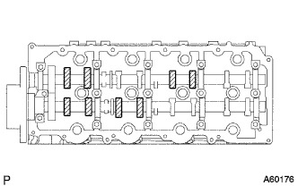
Check only the valves indicated.
-
Using a feeler gauge, measure the clearance between the valve lifter and camshaft.
-
Record the out-of-specification valve clearance measurements. They will be used later to determine the required replacement adjusting shim.
Valve clearance (Cold) Intake 0.20 - 0.30 mm (0.008 - 0.012 in.) Exhaust 0.35 - 0.45 mm (0.014 - 0.018 in.)
-
-
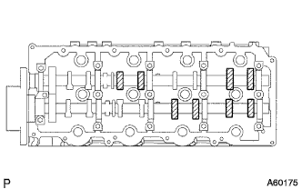
Turn the camshaft 1/2 revolutions (180°).
-
Check only the valves indicated as shown. Measure the valve clearance (See procedure (b) above).
-
-
ADJUST VALVE CLEARANCE
-
Remove the adjusting shim.
-
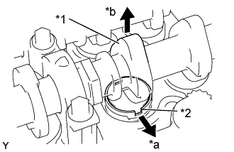
Text in Illustration *1 Cam Lobe *2 Notch *a Manifold Side *b Upward Turn the crankshaft so that the cam lobe of the camshaft on the adjusting valve points upward.
-
Position the notch of the valve lifter facing the manifold side.
-
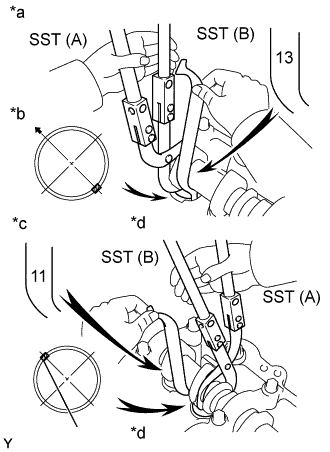
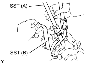
Text in Illustration *a Camshaft Bearing Cap Side *b Bearing Cap Side *c Other Side *d Tip of SST (B) Using SST (A), press down the valve lifter and place SST (B) between the camshaft and valve lifter. Remove SST (A).
- SST
- 09248-55050 ( 09248-05510, 09248-05520 )
Tech Tips
-
Camshaft Bearing Cap Side:
Apply SST (B) on the side marked with "13", at the position shown in the illustration.
-
Other Side:
Apply SST (B) on the side marked with "11", at the position shown in the illustration.
-
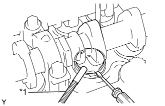
Text in Illustration *1 Magnetic Finger Remove the adjusting shim with a small screwdriver and magnetic finger.
-
-
Determine the replacement adjusting shim size by following the Formula or Charts:
-
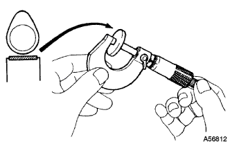
Using a micrometer, measure the thickness of the removed shim.
-
Calculate the thickness of a new shim so that the valve clearance comes within specified value.
T ....... Thickness of removed shim
A ........... Measured valve clearance
N ........... Thickness of new shim
Intake N = T + (A - 0.25 mm (0.010 in.)) Exhaust N = T + (A - 0.40 mm (0.016 in.)) -
Select a new shim with a thickness as close as possible to the calculated value.
Tech Tips
Shims are available in 17 sizes in increments of 0.025 mm (0.0010 in.), from 2.525 mm (0.0994 in.) to 3.300 mm (0.1299 in.).
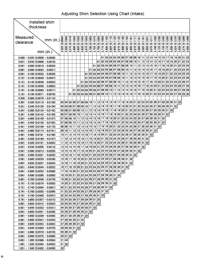
Intake valve clearance (Cold) 0.20 - 0.30 mm (0.0079 - 0.0118 in.) EXAMPLE The 2.800 mm (0.1102 in.) shim is installed, and the measured clearance is 0.350mm (0.0138 in.). Replace the 2.800 mm (0.1102 in.) shim with a new No. 16 shim. New shim thickness mm (in.) No. Shim mark Thickness No. Shim mark Thickness 01 2525 2.525 (0.0994) 17 2925 2.925 (0.1152) 02 2550 2.550 (0.1004) 18 2950 2.950 (0.1161) 03 2575 2.575 (0.1014) 19 2975 2.975 (0.1171) 04 2600 2.600 (0.1024) 20 3000 3.000 (0.1181) 05 2625 2.625 (0.1033) 21 3025 3.025 (0.1191) 06 2650 2.625 (0.1033) 22 3050 3.050 (0.1201) 07 2675 2.675 (0.1053) 23 3075 3.075 (0.1211) 08 2700 2.700 (0.1063) 24 3100 3.100 (0.1220) 09 2725 2.725 (0.1073) 25 3125 3.125 (0.1230) 10 2750 2.750 (0.1083) 26 3150 3.150 (0.1240) 11 2775 2.775 (0.1093) 27 3175 3.175 (0.1250) 12 2800 2.800 (0.1102) 28 3200 3.200 (0.1260) 13 2825 2.825 (0.1112) 29 3225 3.225 (0.1270) 14 2850 2.850 (0.1122) 30 3250 3.250 (0.1280) 15 2875 2.875 (0.1132) 31 3275 3.275 (0.1289) 16 2900 2.900 (0.1142) 32 3300 3.300 (0.1299) 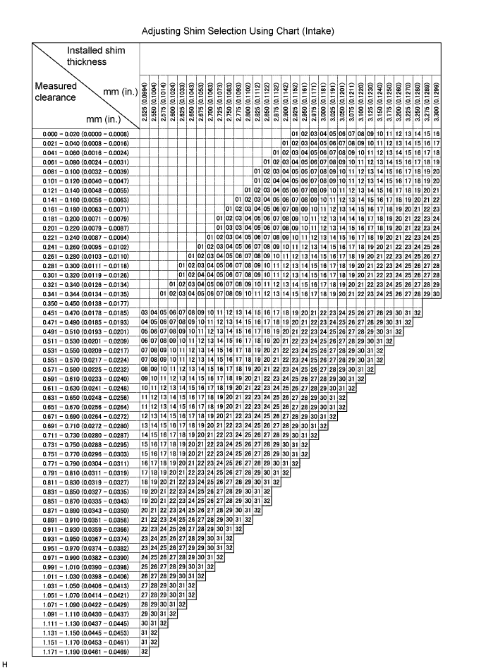
Exhaust valve clearance (Cold) 0.35 - 0.45 mm (0.0138 - 0.0177 in.) EXAMPLE The 2.800mm(0.1102 in.) shim is installed and the measured is 0.350 mm (0.0138 in.). Replace the 2.800 mm (0.1102 in.) shim with a No. 11 shim. The 2.800 mm (0.1102 in.) shim is installed, and the measured clearance is 0.500mm (0.0197 in.). Replace the 2.800 mm (0.1102 in.) shim with a new No. 16 shim. New shim thickness mm (in.) No. Shim mark Thickness No. Shim mark Thickness 01 2525 2.525 (0.0994) 17 2925 2.925 (0.1152) 02 2550 2.550 (0.1004) 18 2950 2.950 (0.1161) 03 2575 2.575 (0.1014) 19 2975 2.975 (0.1171) 04 2600 2.600 (0.1024) 20 3000 3.000 (0.1181) 05 2625 2.625 (0.1033) 21 3025 3.025 (0.1191) 06 2650 2.625 (0.1033) 22 3050 3.050 (0.1201) 07 2675 2.675 (0.1053) 23 3075 3.075 (0.1211) 08 2700 2.700 (0.1063) 24 3100 3.100 (0.1220) 09 2725 2.725 (0.1073) 25 3125 3.125 (0.1230) 10 2750 2.750 (0.1083) 26 3150 3.150 (0.1240) 11 2775 2.775 (0.1093) 27 3175 3.175 (0.1250) 12 2800 2.800 (0.1102) 28 3200 3.200 (0.1260) 13 2825 2.825 (0.1112) 29 3225 3.225 (0.1270) 14 2850 2.850 (0.1122) 30 3250 3.250 (0.1280) 15 2875 2.875 (0.1132) 31 3275 3.275 (0.1289) 16 2900 2.900 (0.1142) 32 3300 3.300 (0.1299)
-
-
Install a new adjusting shim.
-
Place a new adjusting shim on the valve lifter.
-
Using SST (A), press down the valve lifter and remove SST (B).
- SST
- 09248-55050 ( 09248-05510, 09248-05520 )
-
-
Recheck the valve clearance.
-
-
INSTALL INJECTOR ASSEMBLY
Note
-
On installation, clean up the seal surface of the injector and leakage pipe with clean light oil.
-
If the injectors are replaced, replace injection pipes, too.
-
Install 4 new nozzle seats to the cylinder head.
-
Text in Illustration *1 Spring *2 New O-ring *3 Back-up Ring *a Upward *b Connector side Install the spring to each injector as shown in the illustration.
-
Install a new back-up ring to each injector as shown in the illustration.
-
Apply a light coat of oil onto the O-ring to the each injector.
-
Apply a light coat of clean engine oil to a new O-ring and install it to each injector.
-
Insert the 4 injectors into the cylinder head.
Note
-
At this time, insert the injector until it touches the nozzle sheet surface.
-
When installing the injector to the cylinder head, if the injector comes to float up with the reaction of O-ring, pull out the injector once and install it again.
-
Do not exchange the injector.
-
-
Text in Illustration *1 Washer *a Downward Temporarily install each holder clamp with the washer and bolt.
Tech Tips
Apply a light coat of engine oil on the threads and under the heads of the bolts.
-
Install the common rail with the 3 bolts.
- Torque:
- 38 N*m { 387 kgf*cm, 28 ft.*lbf }
-
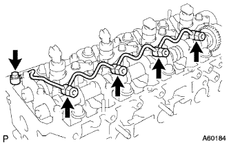
Temporarily install the 4 injection pipes.
Tech Tips
For positioning the injectors, temporarily tighten the union nut.
-
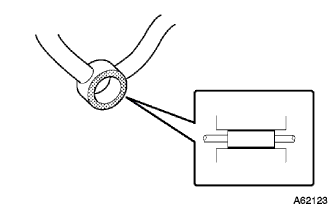
Check, before installing the nozzle leakage pipe using a straight edge, that there is no scratch and deformation (dent) on the seal surface of the unions (at five positions).
In case of having any scratch or deformation, change it to a new one.
-
Place the leakage pipe and 5 new gaskets.
-
Apply a light coat of oil onto the 4 hollow screws and union bolt.
-
Temporarily install the leakage pipe with the 4 hollow screws and union bolt.
-
Tighten the 4 holder clamp bolts.
- Torque:
- 21.6 N*m { 220 kgf*cm, 16 ft.*lbf }
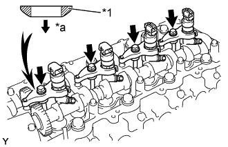
Note
-
Clip the injector at the fork portion with a clamp which is set on the head of the cam cap bolt. At this time, check that the clamp does not hold the injector at the part where the spring is attached.
-
To torque the clamp bolt, temporarily torque it with hand until the bearing surface of the bolt touches the washer, then tighten it by the specified torque.
-
When tightening the bolt by the specified torque, pay attention not to tilt the bolt and the clamp.
-
Tighten the 4 hollow screws and union bolt.
- Torque:
- Hollow screw
- 16 N*m { 163 kgf*cm, 12 ft.*lbf }
- Union bolt
- 12.5 N*m { 127 kgf*cm, 9 ft.*lbf }
Note
In case of over-torque, the nozzle leakage pipe can not be reused, so change it to a new one.
-
Remove the 4 injection pipes.
-
Remove the 3 bolts and common rail.
-
Remove the 2 nuts and supply pump.
-
Check that there are no leaks from the nozzle leakage pipe connection.
-
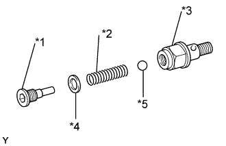
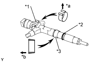
Text in Illustration *1 Plug *2 Spring *3 Overflow Screw *4 Gasket *5 Ball Purchase a new check valve.
Part No. 23122 -27010
-
Remove the plug, gasket, spring and ball.
-
Install the plug with the gasket to the overflow screw.
- Torque:
- 9.8 N*m { 100 kgf*cm, 87 in.*lbf }
-
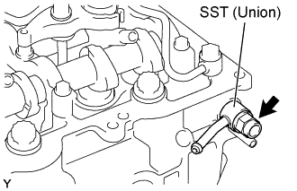
Install the gasket and SST (union) to the cylinder head with the check valve.
- SST
- 09268-45014 ( 90405-06167 )
- Torque:
- 21 N*m { 214 kgf*cm, 15 ft.*lbf }
-
Apply a light coat of soapy water (any fluid to detect fuel leakage) on the nozzle leakage pipe connection.
-
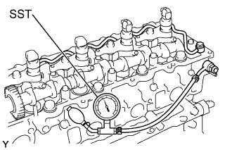
Using SST (turbocharger pressure gauge), apply the SST to the fuel return side of the leakage pipe, and maintain 100 kPa (1.0 kgf*cm2, 14.5 psi) of pressure for 60 seconds to check that there are no bubbles come out.
- SST
- 09992-00242
Note
When checking the leakage, be sure to remove the ball and spring in the check valve before operating.
-
After checking fuel leaks, wipe off soapy water from the leakage pipe connection.
-
Remove the SST, the check valve and gasket.
- SST
- 09992-00242
- 09268-45014 ( 90405-06167 )
- 09992-00242
Tech Tips
Never reinstall the disassembled check valve on the engine.
-
-
-
INSTALL CYLINDER HEAD COVER SUB-ASSEMBLY
-
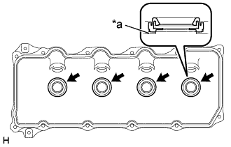
Text in Illustration *a Upper Side of Cylinder Head Cover Install 4 new No. 3 cylinder head cover gaskets to the cylinder head cover as shown in the illustration.
Note
-
Do not install the gaskets at an angle.
-
Keep the lip of the gasket free from foreign materials.
-
-
Install a new cylinder head cover gasket to the cylinder head cover.
-
Text in Illustration *a Seal Packing Apply seal packing to the cylinder head as shown in the illustration.
Seal packing: Toyota Genuine Seal Packing Black, Three Bond 1207B or equivalent -
Install the cylinder head cover with 10 bolts and 2 nuts. Uniformly tighten the bolts and nuts in several passes.
- Torque:
- 9.0 N*m { 92 kgf*cm, 80 in.*lbf }
-
-
INSTALL NOZZLE HOLDER SEAL
-
Install 4 new holder seals.
-
-
INSTALL OIL FILLER CAP SUB-ASSEMBLY