ENGINE UNIT DISASSEMBLY

-
REMOVE OIL FILLER CAP SUB-ASSEMBLY
-
REMOVE NOZZLE HOLDER SEAL
-
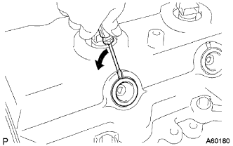
Using a small screwdriver, remove the holder seal by prying the portion between the holder seal and the cutout part of the cylinder head.
-
-
REMOVE CYLINDER HEAD COVER SUB-ASSEMBLY
-
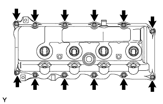
Remove the 10 bolts, 2 nuts, cylinder head cover and the cylinder head cover gasket.
-
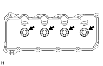
Remove the 4 No. 3 cylinder head cover gaskets from the cylinder head cover.
-
-
REMOVE INJECTOR ASSEMBLY
-
Remove the 4 bolts, washers and nozzle holder clamp.
-
Remove the 4 hollow screws, union bolt, 5 gaskets and nozzle leakage pipe.
-
Remove the 4 injectors and nozzle seats.
Tech Tips
Arrange the injectors in correct order.
-
Remove the spring, O-ring and back-up ring from 4 injectors.
-
-
REMOVE CAMSHAFT TIMING PULLEY
-
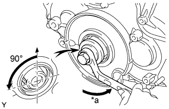
Text in Illustration *a Turn Set the No. 1 cylinder to approx. 90° BTDC/compression.
Tech Tips
Set the No.1 cylinder to 90° BTDC/compression to avoid interference with the piston top and valve head.
-
Using the crankshaft pulley bolt, turn the crankshaft 90° counterclockwise.
-
-
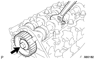
Hold the hexagon wrench head portion of the camshaft, and remove the bolt and timing pulley.
-
-
REMOVE TIMING BELT NO. 2 COVER
-
Remove the nut, 4 bolts and timing belt cover.
-
-
REMOVE CAMSHAFT
-
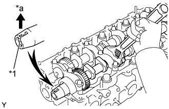
Text in Illustration *1 Key Groove *a Upward Set the key groove of the camshaft, facing upward by turning the camshaft with a wrench.
-
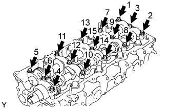
Uniformly loosen and remove the 15 bearing cap bolts, in several passes, in the sequence shown.
-
Remove the 5 bearing caps, oil seal and 2 camshafts.
-
-
REMOVE CYLINDER HEAD SUB-ASSEMBLY
-
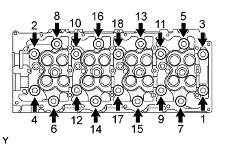
Uniformly loosen and remove the 18 cylinder head bolts, in several passes, in the sequence shown.
Note
Head warpage or cracking could result from removing bolts in incorrect order.
-
Lift the cylinder head from the dowels on the cylinder block, and place the cylinder head on wooden blocks on a bench.
Tech Tips
If the cylinder head is difficult to lift off, pry with a screwdriver between the cylinder head and block.
Note
Be careful not to damage the contact surfaces of the cylinder head and cylinder block.
-
-
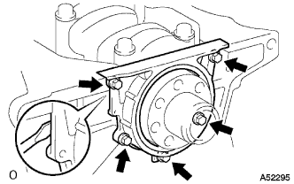
REMOVE WATER PUMP ASSEMBLY
-
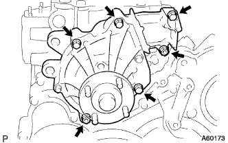
Remove the 5 bolts, 2 nuts, water pump and gasket.
-
-
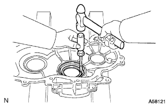
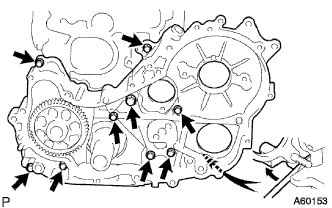
REMOVE TIMING GEAR COVER
-
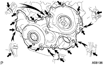
Remove the 14 bolts and 2 nuts.
-
Pry the gear cover as shown in the illustration, and remove the gear cover together with the supply pump drive gear.
Note
Be careful not to drop the supply pump gear.
-
Remove the O-ring from the timing belt cover.
-
-
REMOVE INJECTION GEAR
-
REMOVE CRANKSHAFT POSITION SENSOR PLATE NO.1
-
REMOVE TIMING GEAR COVER OIL SEAL (for Injection Gear)
Tech Tips
There are 2 methods ((a) and (b)) to remove the oil seal.
-
If the timing gear cover is removed from the cylinder block:
-
Using a screwdriver and hammer, tap out the oil seal.
-
-
If the timing gear cover is installed to the cylinder block:
-
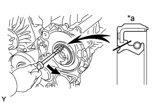
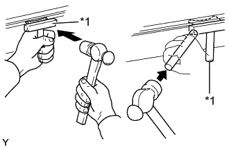
Text in Illustration *1 Cut Position Using a knife, cut off the oil seal lip.
-
Using a screwdriver, pry out the oil seal.
Note
Be careful not to damage the crankshaft. Tape the screwdriver tip.
-
-
-
REMOVE TIMING GEAR COVER OIL SEAL (for Crankshaft Front)
Tech Tips
there are 2 methods ((a) and (b)) to remove the oil seal.
-
If the timing gear cover is removed from the cylinder block:
-
Using a screwdriver and hammer, tap out the oil seal.
-
-
If the timing gear cover is installed to the cylinder block:
-
Using SST, remove the oil seal.
- SST
- 09308-10010
- 09950-40011 ( 09957-04010 )
- 09950-60010 ( 09951-00350 )
-
-
-
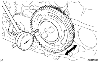
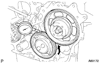
INSPECT BACKLASH OF OIL PUMP GEAR TO CRANKSHAFT TIMING GEAR
-
Using a dial indicator, measure the backlash.
Standard gear backlash 0.02 - 0.15 mm (0.0008 - 0.0060 in.) Maximum gear backlash 0.20 mm (0.0079 in.) If the gear backlash is greater than maximum, replace the gears as a set.
-
-
INSPECT IDLE GEAR NO. 1 THRUST CLEARANCE
-
Using a dial indicator, measure the thrust clearance.
Standard thrust clearance 0.06 - 0.11 mm (0.0024 - 0.0043 in.) Maximum thrust clearance 0.30 mm (0.0118 in.) If the thrust clearance is greater than maximum, replace the thrust plate. If necessary, replace the idle gear and/or idle gear shaft.
-
-
REMOVE IDLE GEAR NO.1
-
Remove the 2 bolts and thrust plate.
-
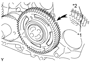
Text in Illustration *1 Main Gear *2 Sub Gear Turn the sub gear and align the gear teeth of the driven main gear and sub gear.
-
Remove the idle gear and sub gear.
-
Remove the idle gear shaft.
-
-
REMOVE IDLE SUB GEAR NO.2
-
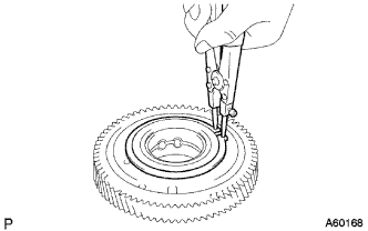
Using snap ring pliers, remove the snap ring.
-
Remove the wave washer, sub gear and gear spring.
-
-
INSPECT BACKLASH OF CRANKSHAFT TIMING GEAR TO IDLE GEAR NO. 1
-
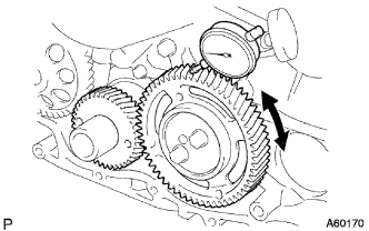
Install the idle gear.
-
Using a dial indicator, measure the backlash.
Standard gear backlash 0.02 - 0.15 mm (0.0008 - 0.0060 in.) Maximum gear backlash 0.20 mm (0.0079 in.) If the gear backlash is greater than maximum, replace the gears as a set.
-
Remove the idle gear.
-
-
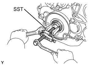
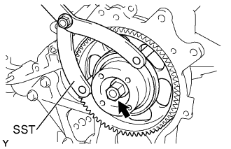
REMOVE CRANKSHAFT TIMING GEAR OR SPROCKET
-
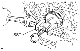
Using SST, remove the crankshaft timing gear.
- SST
- 09950-50013 ( 09951-05010, 09952-05010, 09953-05010, 09954-05021 )
-
-
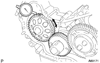
INSPECT BACKLASH OF INJECTION GEAR TO IDLE GEAR NO. 1
-
Install the supply pump with the 2 nuts.
- Torque:
- 21 N*m { 214 kgf*cm, 15 ft.*lbf }
-
Using SST, install the injection gear with the nut.
- SST
- 09960-10010 ( 09962-01000, 09963-01000 )
- Torque:
- 64 N*m { 652 kgf*cm, 47 ft.*lbf }
-
Using a dial indicator, measure the backlash.
Standard gear backlash 0.02 - 0.15 mm (0.0008 - 0.0060 in.) Maximum gear backlash 0.20 mm (0.0079 in.) If the gear backlash is greater than maximum, replace the gears as a set.
-
Using SST, remove the nut and injection gear.
- SST
- 09960-10010 ( 09962-01000, 09963-01000 )
- Torque:
- 64 N*m { 652 kgf*cm, 47 ft.*lbf }
-
Remove the 2 nuts and supply pump.
-
-
REMOVE OIL PAN SUB-ASSEMBLY
-
Remove the 22 bolts and 2 nuts.
-
Text in Illustration *1 Oil Pan Seal Cutter Insert the blade of oil pan seal cutter between the oil pan and cylinder block, and cut off applied sealer and remove the oil pan.
Note
-
Do not use oil pan seal cutter for the timing belt case side and rear oil seal retainer.
-
Be careful not to damage the oil pan flange.
-
-
-
REMOVE OIL STRAINER SUB-ASSEMBLY
-
Remove the 2 bolts, 2 nuts and oil strainer. 25. REMOVE
-
-
REMOVE TIMING GEAR CASE ASSEMBLY
-
Remove the union bolt and 8 bolts.
-
Pry the gear case as shown in the illustration, and remove the gear case, driven rotor and gasket.
-
Remove the 2 O-rings.
-
-
REMOVE ENGINE REAR OIL SEAL RETAINER
-
Remove the union bolt and 8 bolts.
-
Pry the gear case as shown in the illustration, and remove the gear case, driven rotor and gasket.
-
Remove the 2 O-rings.
-
-
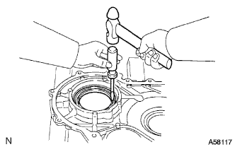
REMOVE ENGINE REAR OIL SEAL
-
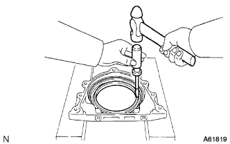
Using a screwdriver and hammer, tap out the oil seal.
-
-
REMOVE INJECTION GEAR BEARING
-
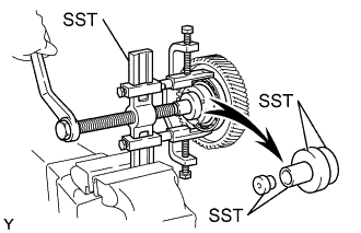
Using SST, remove the bearing.
- SST
- 09950-40011 ( 09951-04020, 09952-04010, 09953-04030, 09954-04010, 09955-04061, 09957-04010, 09958-04011 )
- 09950-60010 ( 09951-00390, 09951-00460, 09952-06010 )
-