ENGINE ASSEMBLY INSTALLATION

-
INSTALL REAR END PLATE
- Torque:
- 8 N*m { 82 kgf*cm, 71 in.*lbf }
-
INSTALL FLYWHEEL SUB-ASSEMBLY
-
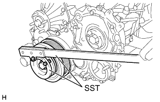
Using SST, fix the crank shaft pulley.
- SST
- 09213-58012
- 09330-00021
-
Apply adhesive to 2 or 3 threads of the mounting bolt end.
Adhesive Toyota Genuine Adhesive 1344, Three Bond 1344 or Equivalent -
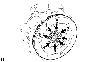
Install the bolts, as shown in the illustration.
- Torque:
- 178 N*m { 1816 kgf*cm, 131 ft.*lbf }
Note
Do not start the engine within 1 hour after the installation.
-
-
INSTALL CLUTCH DISC ASSEMBLY
-
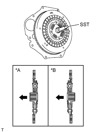
Text in Illustration *A 5L *B 2KD-FTV 
Engine side Insert SST in the clutch disc, then insert them in the flywheel.
- SST
- 09301-00110
Note
Take care not to insert clutch disc in the wrong direction.
-
-
INSTALL CLUTCH COVER ASSEMBLY
-
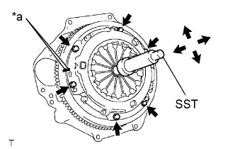
Text in Illustration *a Matchmark Align the matchmarks on the clutch cover and the flywheel.
-
Following the procedures shown in the illustration, tighten the 6 bolts, in the order starting the bolt locating near the knock pin on the top.
- Torque:
- 19.1 N*m { 195 kgf*cm, 14 ft.*lbf }
Tech Tips
-
Following the order in the illustration, tighten the bolts at a time evenly.
-
Move SST up and down, right and left lightly, after checking that the disc is in the center, tighten the bolts.
- SST
- 09301-00110
-
-
INSTALL MANUAL TRANSMISSION UNIT ASSEMBLY
for G54 Manual Transmission
for R451 Manual Transmission
-
INSTALL STARTER ASSEMBLY
for 2.0 kW Type
for 2.7 kW Type
-
INSTALL ENGINE WIRE
-
INSTALL ENGINE W/TRANSMISSION ASSEMBLY
-
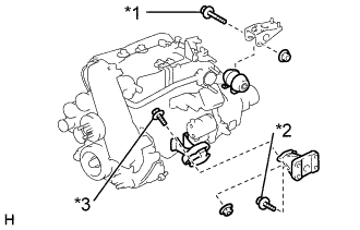
Text in Illustration *1 Bolt A *2 Bolt B *3 Bolt C Using an engine lifter, install the engine assembly with transmission.
- Torque:
- Bolt A
- 98 N*m { 1,000 kgf*cm, 72 ft.*lbf }
- Bolt B
- 61 N*m { 622 kgf*cm, 45 ft.*lbf }
- Bolt C
- 42 N*m { 430 kgf*cm, 31 ft.*lbf }
-
-
INSTALL FRONT SUSPENSION MEMBER ASSEMBLY
-
Using an engine lifter, install the front suspension member assembly with the 4 bolts.
- Torque:
- 150 N*m { 1530 kgf*cm, 110 ft.*lbf }
-
Install the front stabilizer cover RH and LH.
- Torque:
- 18 N*m { 185 kgf*cm, 13 ft.*lbf }
-
Install the front shock absorber assembly RH and LH at the lower arm part.
- Torque:
- 105 N*m { 1070 kgf*cm, 77 ft.*lbf }
-
-
INSTALL PRESSURE FEED TUBE ASSEMBLY
-
INSTALL VANE PUMP ASSEMBLY
-
INSTALL VANE PUMP OIL RESERVOIR ASSEMBLY
-
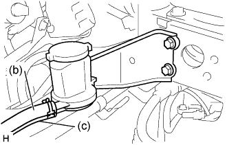
Install the oil reservoir with bracket and 2 bolts.
-
Connect the pressure feed tube.
-
Connect the return tube.
-
-
INSTALL STEERING TORQUE SHAFT ASSEMBLY
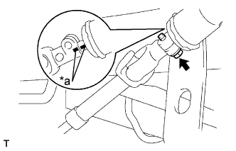
Text in Illustration *a Matchmark
-
Align the matchmarks on the torque shaft and bevel gear.
-
Tighten the bolt.
- Torque:
- 35 N*m { 357 kgf*cm, 26 ft.*lbf }
-
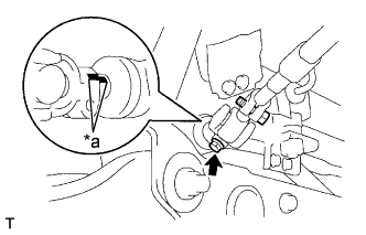
Text in Illustration *a Matchmark Align the matchmarks on the sliding yoke and steering gear.
-
Tighten the bolt.
- Torque:
- 35 N*m { 357 kgf*cm, 26 ft.*lbf }
-
-
INSTALL FRONT SPRING BUMPER NO.1
-
Install the front spring bumper No. 1 RH and LH and nut.
- Torque:
- 120 N*m { 1225 kgf*cm, 88 ft.*lbf }
-
-
INSTALL TIE ROD END SUB-ASSEMBLY LH
-
Connect the tie rod end to the knuckle arm.
-
Install the nuts and new cotter pin.
- Torque:
- 91 N*m { 928 kgf*cm, 67 ft.*lbf }
-
-
INSTALL TIE ROD END SUB-ASSEMBLY RH
Tech Tips
Connect the RH side by the same procedures with the LH side.
-
INSTALL CLUTCH RELEASE CYLINDER ASSEMBLY
-
INSTALL PROPELLER SHAFT ASSEMBLY REAR
for 2 Joint Type
for 3 Joint Type
-
INSTALL ENGINE WIRE
-
INSTALL INTAKE AIR CONNECTOR
-
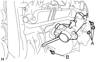
Install the intake air connector with diesel throttle body assembly, new gasket, 2 bolts and 2 nuts.
- Torque:
- A
- 20 N*m { 204 kgf*cm, 15 ft.*lbf }
- B
- 19 N*m { 194 kgf*cm, 14 ft.*lbf }
-
Connect the connector and hose.
-
Connect the throttle control motor connector.
-
Connect the throttle full switch connector.
-
Connect the Intake air temp. sensor connector.
-
Connect the vacuum hose.
-
-
-
INSTALL TURBOCHARGER SUB-ASSEMBLY
-
INSTALL EXHAUST PIPE ASSEMBLY FRONT
-
INSTALL AIR CLEANER HOSE NO.2
-
INSTALL AIR CLEANER PIPE
-
INSTALL FUEL HOSE ALL (ENGINE ROOM)
-
INSTALL RADIATOR ASSEMBLY
-
INSTALL FLUID COUPLING ASSEMBLY
-
Insert the fan shroud and the fan with coupling simultaneously
-
Install the fan with coupling with the 4 nuts.
- Torque:
- 18 N*m { 184 kgf*cm, 13 ft.*lbf }
-
Install the fan shroud with the 2 bolts.
-
-
INSTALL RADIATOR HOSE OUTLET
-
INSTALL RADIATOR HOSE INLET
-
INSTALL AIR HOSE NO.3
-
INSTALL AIR HOSE NO.1
-
INSTALL REAR HEATER WATER INLET HOSE A (FROM ENGINE)
-
INSTALL HEATER WATER OUTLET HOSE A (FROM HEATER UNIT)
-
INSTALL FAN AND GENERATOR V BELT
-
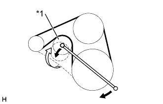
Text in Illustration *1 Auto Tensioner Set the V belt to everything except the auto tensioner, as shown in the illustration.
-
Loosen the V belt by turning the belt tensioner clockwise.
-
Then set the V belt to the auto tensioner.
-
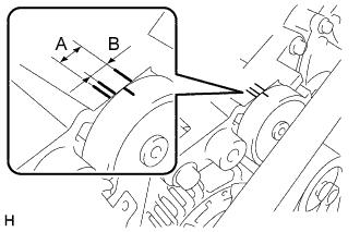
After a new belt has been installed, check that the mark is within the B range as shown in the illustration.
-
-
INSTALL FENDER SIDE APRON SUB-ASSEMBLY LH
-
INSTALL FENDER SIDE APRON SUB-ASSEMBLY RH
-
INSTALL ENGINE SIDE COVER SUB-ASSEMBLY LH
-
INSTALL ENGINE SIDE COVER SUB-ASSEMBLY RH
-
INSTALL ENGINE SERVICE HOLE SUB COVER SUB-ASSEMBLY (W/O TILT CAB CAB TYPE)
- Torque:
- 11.5 N*m { 115 kgf*cm, 8.5 ft.*lbf }
-
INSTALL PARKING BRAKE SHOE LEVER SUB-ASSEMBLY (W/O TILT CAB CAB TYPE)
-
INSTALL TRANSMISSION FLOOR SHIFT ASSEMBLY (W/O TILT CAB CAB TYPE)
for G54 Manual Transmission
for R451 Manual Transmission
-
INSTALL FLOOR SHIFT CABLE TRANSMISSION CONTROL SHIFT
-
Install the control cable with clip and nut.
- Torque:
- 12 N*m { 120 kgf*cm, 9 ft.*lbf }
-
-
INSTALL FLOOR SHIFT CABLE TRANSMISSION CONTROL SELECT
-
Install the control cable with clip and nut.
- Torque:
- 12 N*m { 120 kgf*cm, 9 ft.*lbf }
-
-
INSTALL FRONT SEAT ASSEMBLY (DRIVER SEAT) (W/O TILT CAB CAB TYPE)
-
INSTALL FRONT SEAT ASSEMBLY RH (W/O TILT CAB CAB TYPE)
-
INSTALL BATTERY NEGATIVE TERMINAL
-
REFILL ENGINE COOLANT
-
Slowly fill the system with coolant.
-
Use of improper coolants may damage engine cooling system.
-
Use "Toyota Long Life Coolant" or equivalent and mix it with plan water according to the manufacturer's directions.
-
Using of coolant which includes more than 50 % [freezing protection down to -35°C (-31°F)] or 60 % [freezing protection down to -50°C (-58°F)] of ethylene-glycol is recommended but not more than 70 %.
Note
-
Do not use an alcohol type coolant or plain water alone.
-
The coolant should be mixed with plain water (preferably demineralized water or distilled water).
Capacity: w/ Front heater
w/o heater
10.1 liters (10.5 US qts, 8.7 Imp. qts)
9.2 liters (9.51 US qts, 7.9 Imp. qts)
w/ Front and Rear
heater
10.9 liters (11.5 US qts, 8.9 Imp. qts)
-
-
Reinstall the radiator cap.
-
Start the engine, and bleed the cooling system.
-
Refill the radiator reservoir with coolant until it reaches the "full" line.
-
-
ADD POWER STEERING FLUID
-
BLEED INJECTION PIPE
-
Move the priming pump of the fuel filter up and down until it becomes hard.
-
-
BLEED POWER STEERING FLUID
-
Check the fluid level.
-
Jack up the front of the vehicle and support it with stands.
-
Turn the steering wheel.
-
With the engine stopped, turn the wheel slowly from lock to lock several times.
-
-
Lower the vehicle.
-
Start the engine.
-
Run the engine at idle for a few minutes.
-
-
Turn the steering wheel.
-
With the engine idling, turn the wheel to the left or right full lock position and keep it there for 2 - 3 seconds. Then turn the wheel to the opposite full lock position and keep it there for 2 - 3 seconds (step A).
-
Repeat step A several times.
-
-
Stop the engine.
-
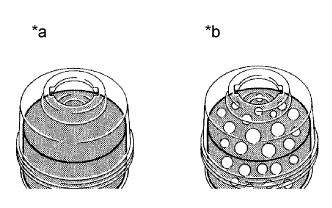
Text in Illustration *a Normal *b Abnormal Check for foaming or emulsification.
Especially, if the system has to be bled twice because of foaming or emulsification, check for fluid leakage in the system.
-
Check the fluid level.
-
-
CHECK POWER STEERING FLUID LEAKAGE
-
CHECK ENGINE COOLANT LEAK
-
INSPECT FUEL LEAK
-
CHECK EXHAUST GAS LEAK
-
INSPECT AND ADJUST FRONT WHEEL ALIGNMENT