CYLINDER BLOCK INSPECTION

Tech Tips
-
Thoroughly clean all parts to be assembled.
-
Before installing the parts, apply new engine oil to all sliding and rotating surfaces.
-
Replace all gaskets, O-rings and oil seals with new parts.
-
INSPECT CYLINDER BLOCK OIL ORIFICE
-
Check the oil orifice for damage or clogging.
If necessary, replace the oil orifice.
-
-
INSPECT OIL CHECK VALVE SUB-ASSEMBLY
-
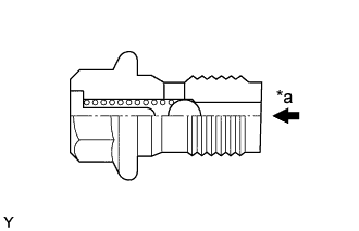
Text in Illustration *a Push Push the valve with a wooden stick to check if it is stuck.
If stuck, replace the check valve.
-
-
INSPECT SUB-ASSEMBLY OIL NOZZLE NO. 1
-
Check the oil nozzles for damage or clogging.
If necessary, replace the oil nozzle.
-
-
INSPECT CYLINDER BLOCK
-
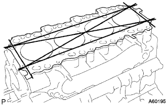
Inspect for flatness.
-
Using a precision straight edge and feeler gauge, measure the surface contacting the cylinder head cap for warpage.
Maximum warpage 0.10 mm (0.0039 in.) If warpage is greater than maximum, replace the cylinder block.
-
-
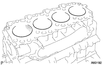
Visually check the cylinder for vertical scratches.
If deep scratches are present, rebore all the 4 cylinders. If necessary, replace the cylinder block.
-
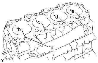
Text in Illustration *a Mark 1, 2 or 3 *b No. 1 *c No. 2 *d No. 3 *e No. 4 Inspect the cylinder bore diameter.
Tech Tips
There are 3 sizes of the standard cylinder bore diameter, marked 1, 2 and 3 accordingly. The mark is stamped on the lower left rear of the cylinder block.
-
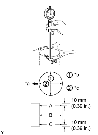
Text in Illustration *a Front *b Thrust Direction *c Axial Direction Using a cylinder gauge, measure the cylinder bore diameter at positions A, B and C in the thrust and axial directions.
Standard diameter Mark 1 92.000 - 92.010 mm (3.6220 - 3.6224 in.) Mark 2 92.010 - 92.020 mm (3.6224 - 3.6228 in.) Mark 3 92.020 - 92.030 mm (3.6228 - 3.6232 in.) Maximum diameter STD 92.23 mm (3.6311 in.) O/S 0.50 92.73 mm (3.6508 in.) If the diameter is greater than maximum, rebore all the 4 cylinders. If necessary, replace the cylinder block.
-
-
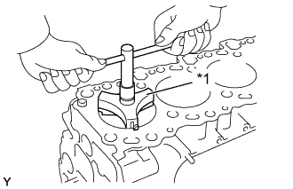
Text in Illustration *1 Ridge Reamer Remove the cylinder ridge.
If the wear is less than 0.2mm (0.008 in.), using a ridge reamer, grind the top of the cylinder.
-
-
INSPECT W/PIN PISTON SUB-ASSEMBLY
Tech Tips
When replacing the piston sub-assembly (w/ pin) with a supply part, there are a number of piston diameter sizes to choose from, but there is only one size of piston pin diameter.
-
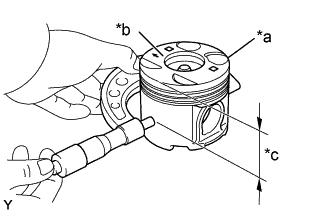
Text in Illustration *a Size Mark *b Front Mark (Arrow) *c Distance Inspect the piston oil clearance.
Tech Tips
There are 3 sizes of the standard piston diameter, marked "1", "2" and "3" accordingly. The mark is stamped on the piston top.
-
Using a micrometer, measure the piston diameter at right angles to the piston center line, the indicated distance from the piston head.
Standard diameter STD Mark 1 91.92 - 91.93 mm (3.6189 - 3.6193 in.) Mark 2 91.93 - 91.94 mm (3.6193 - 3.6197 in.) Mark 3 91.94 - 91.95 mm (3.6197 - 3.6201 in.) O/S 0.50 92.42 - 92.45 mm (3.6386 - 3.6398 in.) -
Measure the cylinder bore diameter in the thrust directions (See step 4).
-
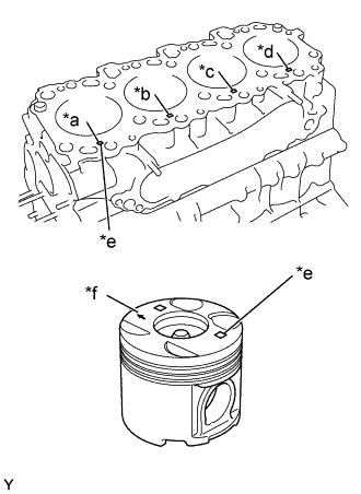
Text in Illustration *a No. 1 *b No. 2 *c No. 3 *d No. 4 *e Mark 1, 2 or 3 *f Front Mark Subtract the piston diameter measurement from the cylinder bore diameter measurement.
Standard oil clearance 0.070 - 0.090 mm (0.0028 - 0.0035 in.) Maximum oil clearance 0.16 mm (0.0063 in.) If the oil clearance is greater than maximum, replace all the 4 pistons and rebore all the 4 cylinders. If necessary, replace the cylinder block.
Tech Tips
Use a piston with the same number mark as the cylinder bore diameter marked on the cylinder block.
-
-
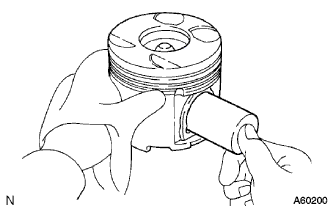
Inspect the piston pin fit.
-
At 60°C (140°F), you should be able to push the piston pin into the piston pin hole with your thumb.
If the pin can be installed at a lower temperature, replace the piston and pin as set.
-
-
Using a micrometer, measure the piston pin diameter.
Piston pin diameter 33.996 - 34.008 mm (1.3384 - 1.3389 in.)
-
-
INSPECT PISTON RING SET
-
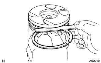
Using a feeler gauge, measure the clearance between a new piston ring and the wall of the ring groove.
Standard groove clearance No. 1 0.060 - 0.100 mm (0.0024 - 0.0039 in.) No. 2 0.050 - 0.090 mm (0.0020 - 0.0035 in.) Oil 0.030 - 0.075 mm (0.0012 - 0.0030 in.) Maximum groove clearance 0.20 mm (0.0079 in.) If the clearance is greater than maximum, replace the piston.
-
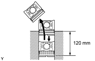
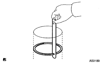
Inspect the piston ring end gap.
-
Insert the piston ring into the cylinder bore.
-
Using a piston, push the piston ring a little beyond the bottom of the ring travel, 120 mm (4.72 in.) from the top of the cylinder block.
-
Using a feeler gauge, measure the end gap.
Standard end gap No. 1 0.270 - 0.510 mm (0.0106 - 0.0201 in.) No. 2 0.470 - 0.740 mm (0.0185 - 0.0291 in.) Oil 0.200 - 0.520 mm (0.0079 - 0.0205 in.) Maximum end gap No. 1 1.21 mm (0.0476 in.) No. 2 1.44 mm (0.0567 in.) Oil 1.22 mm (0.0480 in.) If the end gap is greater than maximum, replace the piston ring. If the end gap is greater than maximum, even with a new piston ring, rebore all the 4 cylinders or replace the cylinder block.
-
-
-
INSPECT CONNECTING ROD SUB-ASSEMBLY
-
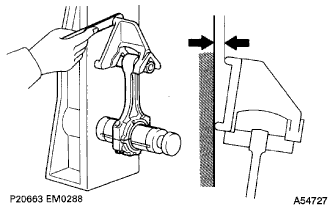
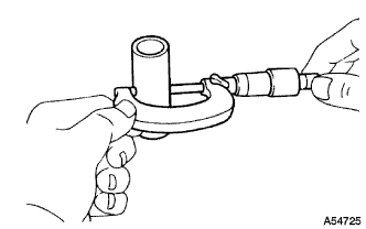
Using a rod aligner and feeler gauge, check the connecting rod alignment.
-
Check for bend.
Maximum bend 0.03 mm (0.0012 in.) per 100 mm (3.94 in.) If bend is greater than maximum, replace the connecting rod sub-assembly.
-
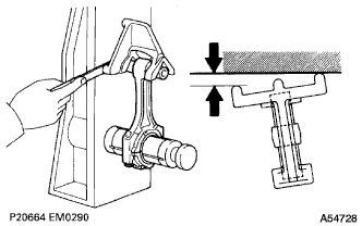
Check for twist
Maximum twist 0.15 mm (0.0059 in.) per 100 mm (3.94 in.) If twist is greater than maximum, replace the connecting rod sub-assembly.
-
-
-
INSPECT PISTON PIN OIL CLEARANCE
-
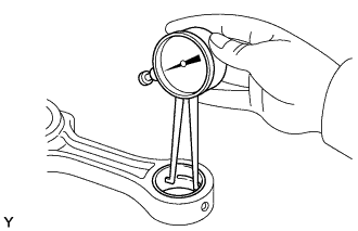
Inspect the piston pin oil clearance.
-
Using a caliper gauge, measure the inside diameter of the connecting rod bush.
Bush inside diameter 34.012 - 34.024 mm (1.3391 - 1.3395 in.) -
Subtract the piston pin diameter measurement (See step 5) from the bush inside diameter measurement.
Standard oil clearance 0.012 - 0.020 mm (0.0005 - 0.0008 in.) Maximum oil clearance 0.03 mm (0.0012 in.) If the oil clearance is greater than maximum, replace the bush.
If necessary, replace the piston and piston pin as a set.
-
-
-
INSPECT CONNECTING ROD BOLT
-
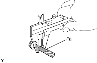
Text in Illustration *a Tension Portion Using vernier calipers, measure the tension portion of the connecting rod bolt.
Standard diameter 8.500 - 8.600 mm (0.3346 - 0.3385 in.) Minimum diameter 8.30 mm (0.3268 in.) If the diameter is less than minimum, replace the bolt.
-
-
BORE CYLINDER
Text in Illustration *a Size Mark *b Front Mark (Arrow) *c Distance Tech Tips
-
Bore all the 4 cylinders for the O/S piston outside diameter.
-
Replace all the piston rings with ones to match the O/S pistons.
-
Keep 4 new O/S pistons.
O/S 0.50 piston diameter 92.42 - 92.45 mm (3.6386 - 3.6398 in.) -
Using a micrometer, measure the piston diameter at right angles to the piston center line, the indicated distance from the piston head.
Distance 65.00 - 65.06 mm (2.5591 - 2.5614 in.) -
Calculate the amount each cylinder is to be rebored as follows:
Size to be rebored = P + C - H P = Piston diameter C = Piston clearance: 0.070 - 0.090 mm (0.0028 - 0.0035 in.) H = Allowance for honing: 0.02mm(0.0008 in.) or less -
Bore and hone the cylinders to calculated dimensions.
Maximum honing 0.02 mm (0.0008 in.) Note
Excess honing will destroy the finished roundness.
-
-
INSPECT CRANKSHAFT
-
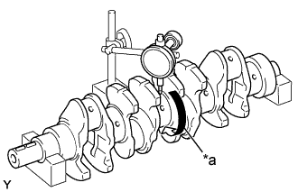
Text in Illustration *a Center Journal Inspect for circle runout.
-
Place the crankshaft on V-blocks.
-
Using a dial indicator, measure the circle runout at the center journal.
Maximum circle runout 0.06 mm (0.0024 in.) If the circle runout is greater than maximum, replace the crankshaft.
-
-
Inspect the main journals and crank pins.
-
Using a micrometer, measure the diameter of each main journal and crank pin.
Main journal diameter STD 69.982 - 70.000 mm (2.7552 - 2.7559 in.) U/S 0.25 69.982 - 70.000 mm (2.7552 - 2.7559 in.) U/S 0.50 69.495 - 69.505 mm (2.7360 - 2.7364 in.) Crank pin diameter STD 58.982 - 59.000 mm (2.3221 - 2.3228 in.) U/S 0.25 58.745 - 58.755 mm (2.3128 - 2.3132 in.) U/S 0.50 58.495 - 58.505 mm (2.3029 - 2.3033 in.) If the diameter is not as specified, check the oil clearance (See steps Click here and Click here). If necessary, grind or replace the crankshaft.
-
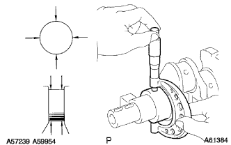
Check each main journal and crank pin for taper and out-of-round as shown.
Maximum taper and out-of-round 0.02 mm (0.0008 in.) If the taper and out-of-round is greater than maximum, replace the crankshaft.
-
-
If necessary, grind and hone the main journals and/or crank pins.
-
Grind and hone the main journals and/or crank pins to the finished undersized diameter (See procedure (b) above).
Install new main journal and/or crankshaft pin undersized bearing.
-
-
-
INSPECT CRANKSHAFT BEARING CAP BOLT
-
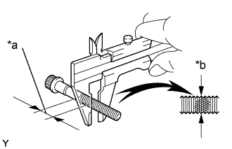
Text in Illustration *a Measuring Point *b Elongated Thread Using vernier calipers, measure the minimum diameter of the compressed thread at the measuring point.
Standard diameter 13.500 - 14.000 mm (0.5315 - 0.5512 in.) Minimum diameter 12.60 mm (0.4961 in.) If the diameter is less than minimum, replace the bolt.
-