CYLINDER BLOCK DISASSEMBLY

Tech Tips
-
Thoroughly clean all parts to be assembled.
-
Before installing the parts, apply new engine oil to all sliding and rotating surfaces.
-
Replace all gaskets, O-rings and oil seals with new parts.
-
REMOVE CYLINDER BLOCK OIL ORIFICE
-
INSPECT CONNECTING ROD THRUST CLEARANCE
-
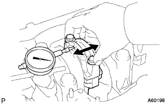
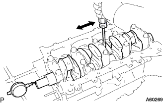
Using a dial indicator, measure the thrust clearance while moving the connecting rod back and forth.
Standard thrust clearance 0.100 - 0.300 mm (0.0039 - 0.0118 in.) Maximum thrust clearance 0.40 mm (0.0157 in.) If the thrust clearance is greater than maximum, replace the connecting rod assembly. If necessary, replace the crankshaft.
-
-
INSPECT CONNECTING ROD OIL CLEARANCE
-
Check the matchmarks on the connecting rod and cap to ensure correct reassembly.
-
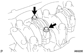
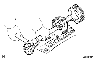
Remove the 2 connecting rod cap bolts.
-
Using the 2 removed connecting rod bolts, pry the connecting rod cap back and forth, and remove the connecting cap.
Tech Tips
Keep the lower bearing inserted with the connecting rod cap.
-
Clean the crank pin and bearing.
-
Check the crank pin and bearing for pitting and scratches.
If the crank pin or bearing is damaged, replace the bearings. If necessary, grind or replace the crankshaft.
-
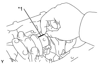
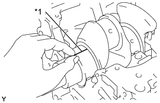
Text in Illustration *1 Plastigage Lay a strip of Plastigage across the crank pin.
-
Install the connecting rod cap with the 2 bolts Click here.
Note
Do not turn the crankshaft.
-
Remove the 2 bolts, connecting rod cap and lower bearing (See procedure (b) and (c) above).
-
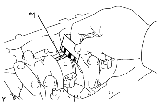
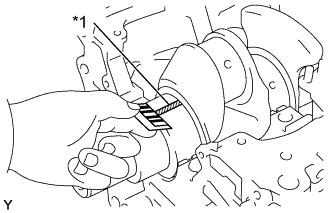
Text in Illustration *1 Plastigage 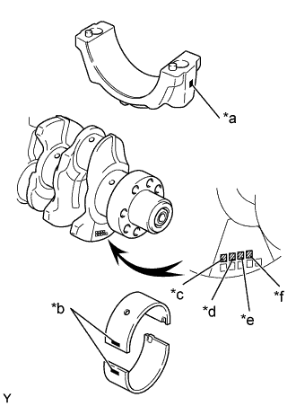
Text in Illustration *a Mark 1, 2 or 3 *b Mark 1, 2 or 3 *c No. 1 *d No. 2 *e No. 3 *f No. 4 Measure the Plastigage at its widest point.
Standard oil clearance STD 0.036 - 0.054 mm (0.0014 - 0.0021 in.) U/S 0.25, U/S 0.50 0.037 - 0.077 mm (0.0015 - 0.0030 in.) Maximum oil clearance 0.10 mm (0.0039 in.) If the oil clearance is greater than maximum, replace the bearings. If necessary, grind or replace the crankshaft.
Tech Tips
If using a standard bearing, replace it with one having the same number. If the number of the bearing cannot be determined, select the correct bearing by adding together the numbers imprinted on the crankshaft and connecting rod, then selecting the bearing with the same number as the total. There are 5 sizes of standard bearings, marked 2, 3, 4, 5 and 6 accordingly.
Item Number Mark Connecting rod cap 1 2 2 Crankshaft 1 2 3 1 2 3 1 2 3 Use bearing 2 3 4 3 4 5 4 5 6 EXAMPLE Connecting rod cap "3" + Crankshaft "1" = Total number 4 (Use bearing "4") Reference Connecting rod big end inner diameter Mark 1 62.014 - 62.020 mm (2.4415 - 2.4417 in.) Mark 2 62.020 - 62.026 mm (2.4417 - 2.4420 in.) Mark 3 62.026 - 62.032 mm (2.4420 - 2.4422 in.) Crankshaft pin diameter Mark 1 58.994 - 59.000 mm (2.3226 - 2.3228 in.) Mark 2 58.988 - 58.994 mm (2.3224 - 2.3226 in.) Mark 3 58.982 - 58.988 mm (2.3221 - 2.3224 in.) Standard sized bearing center wall thickness Mark 2 1.486 - 1.489 mm (0.0585 - 0.0586 in.) Mark 3 1.489 - 1.492 mm (0.0586 - 0.0587 in.) Mark 4 1.492 - 1.495 mm (0.0587 - 0.0589 in.) Mark 5 1.495 - 1.498 mm (0.0589 - 0.0590 in.) Mark 6 1.498 - 1.501 mm (0.0590 - 0.0591 in.) -
Completely remove the Plastigage.
-
-
REMOVE PISTON AND CONNECTING ROD
-
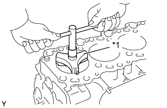
Text in Illustration *1 Ridge Reamer Using a ridge reamer, remove all the carbon from the top of the cylinder.
-
Push the piston, connecting rod assembly and upper bearing through the top of the cylinder block.
Tech Tips
-
Keep the bearings, connecting rod and cap together.
-
Arrange the piston and connecting rod assemblies in correct order.
-
-
-
REMOVE W/PIN PISTON SUB-ASSEMBLY
-
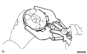
Check fit between the piston and piston pin.
-
Try to move the piston back and forth on the piston pin.
If any movement is felt, replace the piston and pin as a set.
-
-
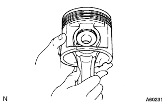
Remove the piston rings.
-
Using a piston ring expander, remove the 2 compression rings.
-
Remove the 2 side rails and oil ring by hand.
Tech Tips
Arrange the piston rings in correct order only.
-
-
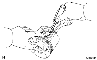
Disconnect the connecting rod from the piston.
-
Using a small screwdriver, pry off the snap ring from the piston.
-
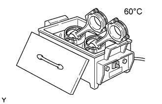
Gradually heat the piston to approx. 60°C (140°F).
-
Using a plastic-faced hammer and brass bar, lightly tap out the piston pin and pin and remove the connecting rod.
Tech Tips
-
The piston and pin are a matched set.
-
Arrange the pistons, pins, rings, connecting rods and bearings in correct order.
-
-
-
-
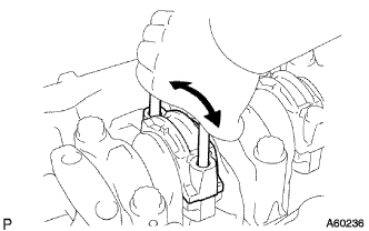
INSPECT CRANKSHAFT THRUST CLEARANCE
-
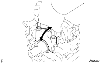
Using a dial indicator, measure the thrust clearance while prying the crankshaft back and forth with a screwdriver.
Standard thrust clearance 0.040 - 0.250 mm (0.0016 - 0.0098 in.) Maximum thrust clearance 0.30 mm (0.0118 in.) If the thrust clearance is greater than maximum, replace the thrust washers as a set.
Thrust washer thickness Thrust washer Thickness STD 2.430 - 2.480 mm (0.0957 - 0.0976 in.) O/S 0.125 2.493 - 2.543 mm (0.0981 - 0.1001 in.) O/S 0.250 2.555 - 2.605 mm (0.1006 - 0.1026 in.)
-
-
INSPECT CRANKSHAFT OIL CLEARANCE
-
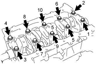
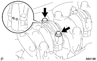
Uniformly loosen and remove the 10 main bearing cap bolts in several passes, in the sequence shown.
-
Using the removed crankshaft bearing cap bolts, pry the cap back and forth, and remove the crankshaft bearing caps, lower crankshaft bearings and lower thrust washers (No. 3 crankshaft bearing cap only).
Tech Tips
-
Keep the lower bearing and crankshaft bearings cap together.
-
Arrange the thrust washers in correct order.
-
-
Lift out the crankshaft.
Tech Tips
Keep the upper crankshaft bearings and upper thrust washers together with the cylinder block.
-
Clean each main journal and bearing.
-
Check each main journal and bearing for pitting and scratches.
If the journal or bearing is damaged, replace the bearings. If necessary, grind or replace the crankshaft.
-
Place the crankshaft on the cylinder block.
-
Text in Illustration *1 Plastigage Lay a strip of Plastigage across each journal.
-
Install the 5 crankshaft bearing caps with the 10 bolts (See step Click here).
NOTICE Do not turn the crankshaft. -
Remove the 10 bolts and 5 crankshaft bearing caps (See procedure (a) and (b) above).
-
Text in Illustration *1 Plastigage Measure the Plastigage at its widest point.
Standard oil clearance STD 0.030 - 0.048 mm (0.0012 - 0.0019 in.) U/S 0.25, U/S 0.50 0.037 - 0.077 mm (0.0015 - 0.0030 in.) Maximum clearance 0.10 mm (0.0039 in.) If the oil clearance is greater than maximum, replace the bearings. If necessary, grind or replace the crankshaft.
Tech Tips
If replacing the cylinder block subassembly, the bearing standard clearance will be:
0.030 - 0.048 mm (0.0012 - 0.0019 in.)
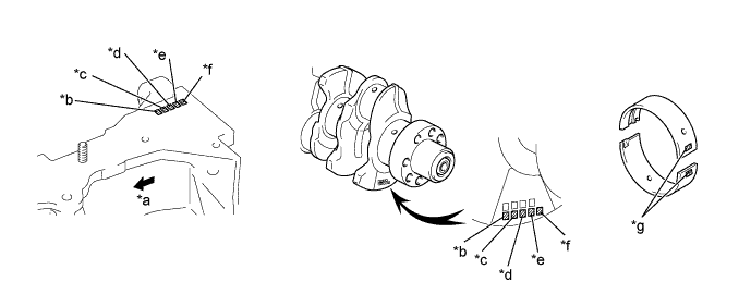
Text in Illustration *a Front *b No. 1 *c No. 2 *d No. 3 *e No. 4 *f No. 5 *g Mark 2, 3, 4, 5 or 6 - - Tech Tips
If using a standard bearing, replace it with one having the same number. If the number of the bearing cannot be determined, select the correct bearing by adding together the numbers imprinted on the cylinder block and crankshaft, then selecting the bearing with the same number as the total. There are 5 sizes of standard bearings, marked 2, 3, 4, 5 and 6 accordingly.
Item Number Mark Connecting rod 1 2 2 Crankshaft 1 2 3 1 2 3 1 2 3 Use bearing 2 3 4 3 4 5 4 5 6 Reference Cylinder block main journal bore diameter Mark 1 75.000 - 75.006 mm (2.9528 - 2.9530 in.) Mark 2 75.006 - 75.012 mm (2.9530 - 2.9532 in.) Mark 3 75.012 - 75. 018 mm (2.9532 - 2.9535 in.) Crankshaft journal diameter Mark 1 69.994 - 70.000 mm (2.7557 - 2.7559 in.) Mark 2 69.988 - 69.994 mm (2.7554 - 2.7557 in.) Mark 3 69.982 - 69.988 mm (2.7552 - 2.7554 in.) Standard sized bearing center wall thickness Mark 2 2.482 - 2.485 mm (0.0977 - 0.0978 in.) Mark 3 2.485 - 2.488 mm (0.0978 - 0.0980 in.) Mark 4 2.488 - 2.491 mm (0.0980 - 0.0981 in.) Mark 5 2.491 - 2.494 mm (0.0981 - 0.0982 in.) Mark 6 2.494 - 2.497 mm (0.0982 - 0.0983 in.) -
Completely remove the Plastigage.
-
-
REMOVE CRANKSHAFT
-
Lift out the crankshaft.
-
Remove the upper bearings and upper thrust washers from the cylinder block.
Tech Tips
Arrange the main bearing caps, bearings and thrust washers in correct order.
-
-
REMOVE SUB-ASSEMBLY OIL NOZZLE NO.1
-
Remove the 4 check valves and oil nozzles.
-
-
REMOVE W/HEAD STRAIGHT SCREW PLUG NO.1
-
Remove the screw plug and gasket.
-
-
CLEAN CYLINDER BLOCK
-
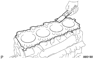
Using a gasket scraper, remove all the gasket material from the top surface of the cylinder block.
-
Using a soft brush and solvent, thoroughly clean the cylinder block.
-
-
CLEAN W/PIN PISTON SUB-ASSEMBLY
-
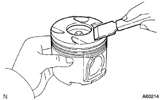
Using a gasket scraper, remove the carbon from the piston top.
-
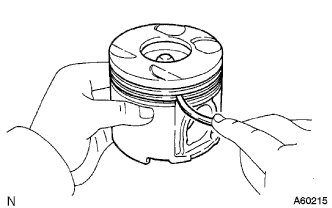
Using a groove cleaning tool or broken ring, clean the piston ring grooves.
-
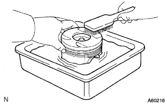
Using solvent and a brush, thoroughly clean the piston.
Note
Do not use a wire brush.
-
-
REMOVE CONNECTING ROD SMALL END BUSH
-
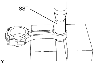
Using SST and a press, press out the bush.
- SST
- 09222-76012
-