CYLINDER HEAD REASSEMBLY

Tech Tips
-
Thoroughly clean all parts to be assembled.
-
Before installing the parts, apply fresh engine oil to all sliding and rotating surfaces.
-
Replace all gaskets and oil seals with new ones.
-
INSTALL INTAKE VALVE GUIDE BUSH
-
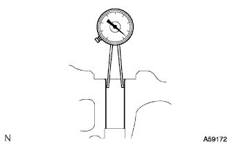
Using a caliper gauge, measure the bush bore diameter of the cylinder head.
-
Select a new guide bush (STD or O/S 0.05).
Bush bore diameter Bush size 10.985 - 11.006 mm (0.4325 - 0.4333 in.) Use STD 11.035 - 11.056 mm (0.4344 - 0.4353 in.) Use O/S 0.05 If the bush bore diameter of the cylinder head is greater than 11.006 mm (0.4333 in.), machine the bush bore to this dimension of 11.035 - 11.056 mm (0.4344 - 0.4353 in.).
If the bush bore diameter of the cylinder head is greater than 11.056 mm (0.4353 in.), replace the cylinder head.
-
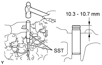
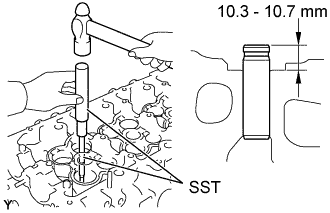
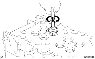
Using SST and a hammer, tap in a new guide bush to the specified protrusion height.
- SST
- 09201-10000 ( 09201-01060 )
- 09950-70010 ( 09951-07100 )
Protrusion height 10.3 - 10.7 mm (0.406 - 0.421 in.) -
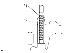
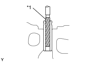
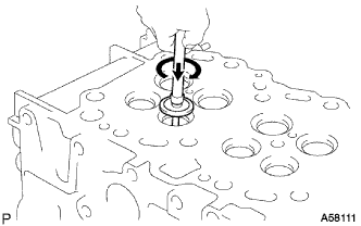
Text in Illustration *1 6.0 mm Reamer Using a sharp 6.0mm reamer, ream the guide bush to obtain the standard specified clearance (See step Click here) between the guide bush and valve stem.
-
-
INSTALL EXHAUST VALVE GUIDE BUSH
-
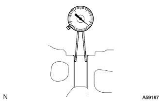
Using a caliper gauge, measure the bush bore diameter of the cylinder head.
-
Select a new guide bush (STD or O/S 0.05).
Bush bore diameter Bush size 10.985 - 11.006 mm (0.4325 - 0.4333 in.) Use STD 11.035 - 11.056 mm (0.4344 - 0.4353 in.) Use O/S 0.05 If the bush bore diameter of the cylinder head is greater than 11.006 mm (0.4333 in.), machine the bush bore to this dimension of 11.035 - 11.056 mm (0.4344 - 0.4353 in.).
If the bush bore diameter of the cylinder head is greater than 11.056 mm (0.4353 in.), replace the cylinder head.
-
Using SST and a hammer, tap in a new guide bush to the specified protrusion height.
- SST
- 09201-10000 ( 09201-01060 )
- 09950-70010 ( 09951-07100 )
Protrusion height 10.3 - 10.7 mm (0.406 - 0.421 in.) -
Text in Illustration *1 6.0 mm Reamer Using a sharp 6.0mm reamer, ream the guide bush to obtain the standard specified clearance (See step Click here) between the guide bush and valve stem.
-
-
REPAIR INTAKE VALVE SEATS
-
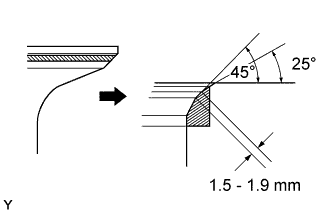
If the seating is too high on the valve face, use 25° and 45° cutters to correct the seat.
-
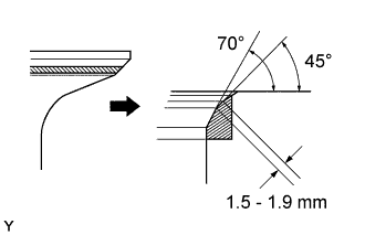
If the seating is too low on the valve face, use 70° and 45° cutters to correct the seat.
-
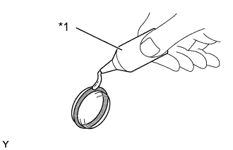
Hand-lap the valve and valve seat with an abrasive compound.
-
After hand-lapping, clean the valve and valve seat.
-
-
REPAIR EXHAUST VALVE SEATS
-
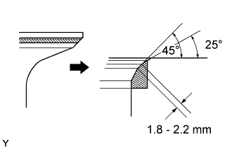
If the seating is too high on the valve face, use 25° and 45° cutters to correct the seat.
-

If the seating is too low on the valve face, use 75° and 45° cutters to correct the seat.
-
Hand-lap the valve and valve seat with an abrasive compound.
-
After hand-lapping, clean the valve and valve seat.
-
-
INSTALL TIGHT PLUG
-
Text in Illustration *1 Adhesive Apply adhesive to a new tight plug.
Adhesive Toyota Genuine Adhesive 1324, Three Bond 1324 or Equivalent -
Using SST and a hammer, tap in the tight plug as shown in the illustration.
Position A
- SST
- 09950-60010 ( 09951-00200 )
- 09950-70010 ( 09951-07100 )
Position B
- SST
- 09950-60010 ( 09951-00230 )
- 09950-70010 ( 09951-07100 )
Position C
- SST
- 09950-60010 ( 09951-00300 )
- 09950-70010 ( 09951-07100 )
Position D
- SST
- 09950-60010 ( 09951-00350 )
- 09950-70010 ( 09951-07100 )
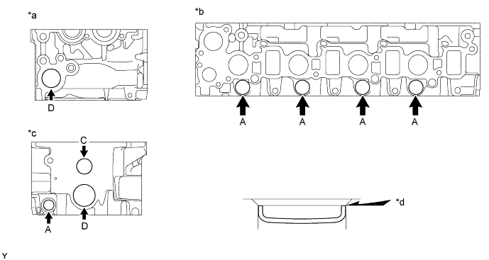
Text in Illustration *a Front Side *b Intake Manifold Side *c Rear Side *d Stops
-
-
INSTALL STUD BOLT
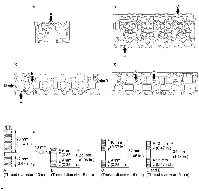
Text in Illustration *a Front Side *b Cylinder Head Cover Side *c Intake Manifold Side *d Exhaust Manifold Side - Torque:
- A
- 26 N*m { 265 kgf*cm, 19 ft.*lbf }
- B
- 15 N*m { 150 kgf*cm, 11 ft.*lbf }
- C and E
- 5 N*m { 50 kgf*cm, 44 in.*lbf }
- D
- 7 N*m { 70 kgf*cm, 62 in.*lbf }
-
INSTALL RING PIN
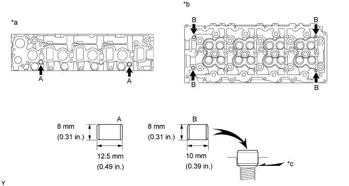
Text in Illustration *a Intake Manifold Side *b Cylinder Head Cover Side *c Until pin stops - - -
INSTALL W/HEAD STRAIGHT SCREW PLUG NO.1
-
Apply adhesive to the end of the screw plug.
Adhesive Toyota Genuine Adhesive 1324, Three Bond 1324 or Equivalent -
Using a 6 mm hexagon wrench, install the screw plug.
Text in Illustration *1 Adhesive - - - Torque:
- 25 N*m { 255 kgf*cm, 18 ft.*lbf }
-
-
INSTALL SEMICIRCULAR PLUG
-
Remove any old packing (FIPG) material and be careful not to drop any oil on the contact surfaces of the semicircular plug and cylinder head.
-
Using a razor blade and gasket scraper, remove all the oil packing (FIPG) material from the gasket surfaces and sealing grooves.
-
Thoroughly clean all components to remove all the loose material.
-
Using a non-residue solvent, clean both sealing surfaces.
-
-
Apply seal packing to the oil seal retainer as shown in the illustration.
Seal packing Toyota Genuine Seal Packing Black, Three Bond 1207B or equivalent
-
Parts must be assembled within 5 minutes of application. Otherwise the material must be removed and reapplied.
-
Immediately remove nozzle from the tube and reinstall cap.
-
-
Install the semi-circular plug to the cylinder head.
Text in Illustration *1 Seal Packing - -
-
-
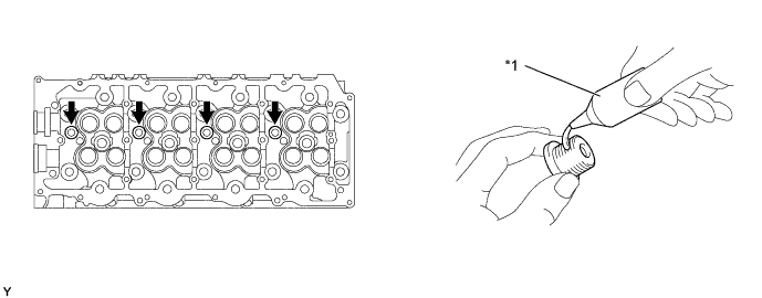
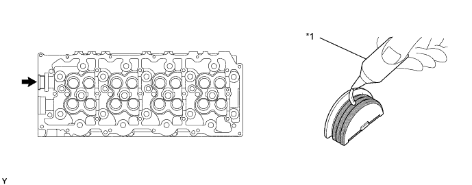
INSTALL VALVE STEM OIL O SEAL OR RING
-
Using SST, push in a new oil seal.
- SST
- 09201-41020
-
-
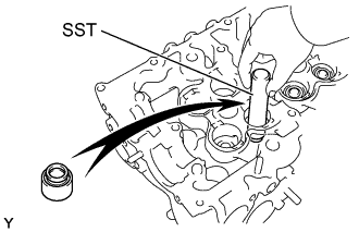
INSTALL INTAKE VALVE
-
Install the valve, spring seat, compression spring and spring retainer.
-
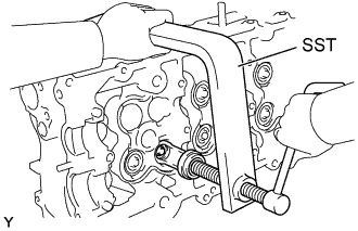
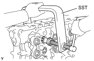
Using SST, compress the compression spring and place the 2 keepers around the valve stem.
- SST
- 09202-70020
- 09202-00020
-
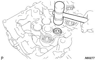
Using a plastic-faced hammer, lightly tap the valve stem tip to assure a proper fit.
Note
Be careful not do damage the valve stem tip.
-
-
INSTALL EXHAUST VALVE
-
Install the valve, spring seat, compression spring and spring retainer.
-
Using SST, compress the compression spring and place the 2 keepers around the valve stem.
- SST
- 09202-70020
- 09202-00020
-
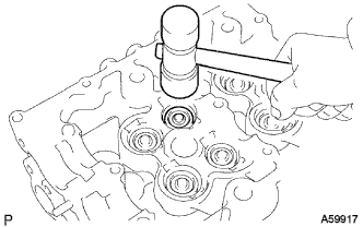
Using a plastic-faced hammer, lightly tap the valve stem tip to assure a proper fit.
Note
Be careful not do damage the valve stem tip.
-
-
INSTALL VALVE LIFTER
-
Install the valve lifter and shim.
-
Check that the valve lifter rotates smoothly by hand.
-