ENGINE UNIT INSTALLATION

-
INSTALL VACUUM PUMP OUTLET UNION
-
Install a new gasket and the outlet union.
-
-
INSTALL VACUUM PUMP INLET UNION
-
Clean the threads of the inlet union apply adhesive there.
Adhesive Toyota Genuine Adhesive 1344, Three Bond 1344 or Equivalent -
Install the inlet union.
-
-
INSTALL ENGINE OIL PRESSURE SWITCH ASSEMBLY
-
Clean the threads of the oil pressure switch, apply adhesive there.
Adhesive Toyota Genuine Adhesive 1344, Three Bond 1344 or Equivalent -
Install the oil pressure switch.
- Torque:
- 15 N*m { 155 kgf*cm, 11 ft.*lbf }
-
-
INSTALL ENGINE OIL LEVEL SENSOR
- Torque:
- 7.0 N*m { 71.4 kgf*cm, 62 ft.*lbf }
-
INSTALL ENGINE COOLANT TEMPERATURE SENSOR
-
Clean the threads of the coolant temperature sensor, apply adhesive there.
Adhesive Toyota Genuine Adhesive 1344, Three Bond 1344 or Equivalent -
Install the coolant temperature sensor.
- Torque:
- 20 N*m { 200 kgf*cm, 15 ft.*lbf }
-
-
INSTALL WATER BY-PASS HOSE UNION
-
Clean the threads of the water by-pass hose union, apply adhesive there.
Adhesive Toyota Genuine Adhesive 1344, Three Bond 1344 or Equivalent -
Install the water by-pass hose union.
- Torque:
- 39 N*m { 400 kgf*cm, 29 ft.*lbf }
-
-
INSTALL INTAKE MANIFOLD
-
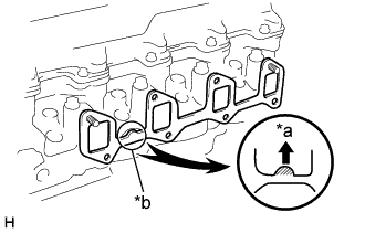
Text in Illustration *a Upward *b Protrusion Install a new gasket to the cylinder head, facing the protrusion upward.
-
Install the intake manifold, 2 engine wire brackets, oil dipstick guide bracket with the 6 bolts and 2 nuts. Uniformly tighten the bolts and nuts in several passes.
- Torque:
- 24.5 N*m { 250 kgf*cm, 17 ft.*lbf }
-
Install the accelerator link and hose clamp (w/ ACSD) with the bolt and nut.
- Torque:
- 19 N*m { 195 kgf*cm, 14 ft.*lbf }
-
Connect the accelerator link to the injection pump.
-
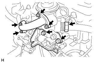
w/ ACSD:
Connect the 2 water by-pass hoses to the hose clamp.
-
-
INSTALL WATER OUTLET HOUSING
-
Install a new gasket, the water outlet and outlet housing assembly with the 3 bolts.
- Torque:
- 19 N*m { 195 kgf*cm, 14 ft.*lbf }
-
Connect the water temperature sender gauge connector.
-
w/ ACSD:
Connect the water by-pass hose to the water housing.
-
-
INSTALL NOZZLE HOLDER AND NOZZLE SET
-
Install a new nozzle sheet gasket and nozzle sheet to the cylinder head.
-
Using SST, install the set of holder and nozzle.
- Torque:
- 64 N*m { 650 kgf*cm, 47 ft.*lbf }
- SST
- 09268-64010 ( 09268-64020 )
-
-
INSTALL NOZZLE LEAKAGE PIPE ASSEMBLY
-
Using a new washer, install the nozzle leakage pipe assembly.
- Torque:
- 29.5 N*m { 300 kgf*cm, 22 ft.*lbf }
-
-
INSTALL GLOW PLUG ASSEMBLY
-
INSTALL GLOW PLUG NO.1 CONNECTOR
-
INSTALL OIL FILTER BRACKET SUB-ASSEMBLY
-
Install a new gasket and oil filter bracket.
- Torque:
- 29.5 N*m { 300 kgf*cm, 22 ft.*lbf }
-
-
INSTALL OIL FILTER SUB-ASSEMBLY
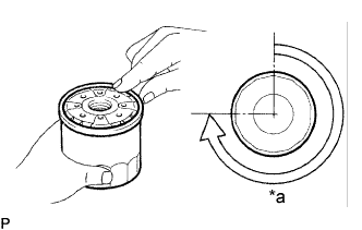
Text in Illustration *a 3/4 Turn
-
Check and clean the oil filter installation surface.
-
Apply clean engine oil to the rubber gasket of a new oil filter.
-
Lightly screw the oil filter into place, and tighten it by hand until the rubber gasket contacts the installation surface.
-
Using SST, tighten it by an additional 3/4 turn to seat the filter.
- SST
- 09228-10002
-
-
INSTALL EXHAUST MANIFOLD
-
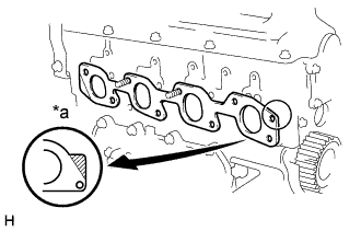
Text in Illustration *a Front Mark Install a new gasket to the cylinder head.
Tech Tips
The direction of a new gasket is in the illustration.
-
Install the exhaust manifold with the 6 bolts and 2 new nuts. Uniformly tighten the bolts and nuts in several passes.
- Torque:
- 52 N*m { 530 kgf*cm, 38 ft.*lbf }
-
-
INSTALL EXHAUST PIPE ASSEMBLY FRONT
-
Install a new gasket to the exhaust pipe.
-
Install the exhaust pipe with the 3 new nuts. Uniformly tighten the nuts.
- Torque:
- 62 N*m { 630 kgf*cm, 46 ft.*lbf }
-
-
INSTALL ELECTRIC EGR CONTROL VALVE ASSEMBLY (w/ EGR)
-
Install a new gasket and EGR pipe to the intake manifold with the 2 bolts.
-
Install a new gasket, EGR valve and EGR pipe with the 2 bolts, 4 nuts and union nut.
- Torque:
- Bolt
- 13 N*m { 130 kgf*cm, 9 ft.*lbf }
- Nut
- 19 N*m { 195 kgf*cm, 14 ft.*lbf }
- Union nut
- 108 N*m { 110 kgf*cm, 79 ft.*lbf }
-
-
INSTALL EXHAUST MANIFOLD HEAT INSULATOR NO.1
-

Install the heat insulator with the 3 bolts.
- Torque:
- A
- 12 N*m { 120 kgf*cm, 9 ft.*lbf }
- B
- 19 N*m { 195 kgf*cm, 14 ft.*lbf }
-
-
INSTALL PUMP BRACKET
-

Install the pump bracket with the 6 bolts.
- Torque:
- A
- 78.5 N*m { 800 kgf*cm, 58 ft.*lbf }
- B
- 57 N*m { 580 kgf*cm, 42 ft.*lbf }
-
-
INSTALL ENGINE MOUNTING BRACKET FRONT NO.1 RH
- Torque:
- 39 N*m { 400 kgf*cm, 29 ft.*lbf }
-
INSTALL INJECTION PUMP ASSEMBLY
-
INSTALL INJECTION PUMP DRIVE PULLEY
-
Using SST, install the injection pump drive pulley.
- SST
- 09213-14010 ( 91651-60865 )
- 09330-00021 ( 09330-00030 )
-
-
INSTALL INJECTION PIPE SUB-ASSEMBLY NO.1
-
INSTALL INJECTION PIPE SUB-ASSEMBLY NO.2
-
INSTALL INJECTION PIPE SUB-ASSEMBLY NO.3
-
INSTALL INJECTION PIPE SUB-ASSEMBLY NO.4
-
INSTALL INJECTION PIPE CLAMP
-
INSTALL FAN BELT ADJUSTING BAR (W/ AIR CONDITIONER)
- Torque:
- 45 N*m { 460 kgf*cm, 33 ft.*lbf }
-
INSTALL GENERATOR ASSEMBLY
-
REMOVE IDLE PULLEY BRACKET (W/ AIR CONDITIONER)
- Torque:
- 46.6 N*m { 466 kgf*cm, 34 ft.*lbf }
-
INSTALL COMPRESSOR MOUNTING BRACKET NO.1 (W/ AIR CONDITIONER)
- Torque:
- 85.6 N*m { 876 kgf*cm, 63 ft.*lbf }
-
INSTALL CYLINDER HEAD COVER NO.2 (w/ Cylinder Head Cover No.2)
-
Install the cylinder head cover with the 4 plate washers and nuts.
- Torque:
- 12 N*m { 120 kgf*cm, 9 ft.*lbf }
-
-
INSTALL OIL FILLER CAP SUB-ASSEMBLY
-
INSTALL INTAKE AIR CONNECTOR BRACKET
- Torque:
- 12 N*m { 120 kgf*cm, 9 ft.*lbf }
-
INSTALL INTAKE AIR CONNECTOR SUB-ASSEMBLY
-
Install a new gasket to the intake manifold.
-
Install the intake air connector with the 3 nuts and bolt.
- Torque:
- 12 N*m { 120 kgf*cm, 9 ft.*lbf }
-
-
INSTALL TIMING BELT
Tech Tips
If re-using the timing belt, align the points marked during removal, and install the timing belt with the arrow pointing in the direction of engine revolution.
-
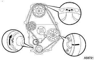
Install the timing belt Click here.
-
-
INSTALL TIMING CHAIN OR BELT COVER SUB-ASSEMBLY
-
Install the collar to the timing pointer.
-
Install the 2 gaskets to the timing belt cover.
-
Install the timing belt cover with the 11 bolts.
- Torque:
- 10.5 N*m { 105 kgf*cm, 8 ft.*lbf }
-
-
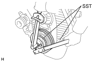
INSTALL CRANKSHAFT PULLEY
-
Align the pulley set key with the key groove of the pulley, and slide the pulley to the crankshaft.
-
Using SST, install the new pulley bolt.
- Torque:
- 235 N*m { 2400 kgf*cm, 173 ft.*lbf }
-
-
INSTALL VANE PUMP DRIVE PULLEY
-
Install the vane pump drive pulley and vane pump pulley spacer with the 4 bolts.
- Torque:
- 19 N*m { 195 kgf*cm, 14 ft.*lbf }
-
w/ A/C
Install the vane pump drive pulley and crankshaft pulley No.2 with the 4 bolts.
- Torque:
- 19 N*m { 195 kgf*cm, 14 ft.*lbf }
-
-
INSTALL ENGINE ASSEMBLY