CYLINDER HEAD GASKET REMOVAL

-
REMOVE TIMING BELT
-
REMOVE AIR CLEANER PIPE
-
REMOVE AIR CLEANER HOSE NO.2
-
REMOVE EXHAUST PIPE ASSEMBLY FRONT
-
REMOVE REAR HEATER WATER INLET HOSE A (FROM ENGINE)
-
REMOVE AIR HOSE NO.1
-
REMOVE TURBOCHARGER SUB-ASSEMBLY
-
REMOVE AIR HOSE NO.3
-
REMOVE HEATER WATER OUTLET HOSE A (FROM HEATER UNIT)
-
REMOVE RADIATOR HOSE OUTLET
-
REMOVE INTAKE AIR CONNECTOR
-
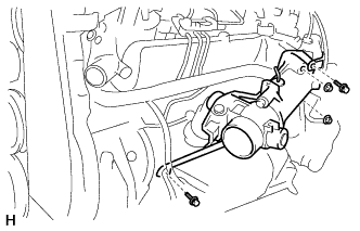
Disconnect the connector and hose.
-
Disconnect the throttle control motor connector.
-
Disconnect the throttle full switch connector.
-
Disconnect the Intake air temp. sensor connector.
-
Disconnect the vacuum hose.
-
-
Remove the 2 bolts, 2 nuts, gasket and intake air connector with diesel throttle body assembly.
-
-
REMOVE CYLINDER HEAD COVER SUB-ASSEMBLY
-
Disconnect the 4 injector connectors.
-
Remove the 2 bolts and disconnect the engine wire protector.
-
Remove the 4 injection pipes Click here.
-
Remove the 4 nozzle holder seals.
-
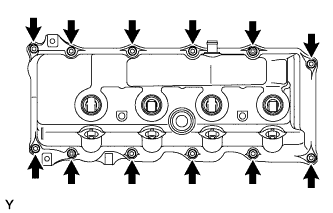
Remove the 10 bolts, 2 nuts, cylinder head cover and the cylinder head cover gasket.
-
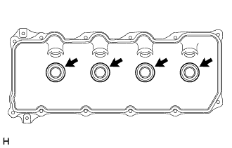
Remove the 4 No. 3 cylinder head cover gaskets from the cylinder head cover.
-
-
REMOVE INJECTOR ASSEMBLY
-
REMOVE CAMSHAFT TIMING PULLEY
-
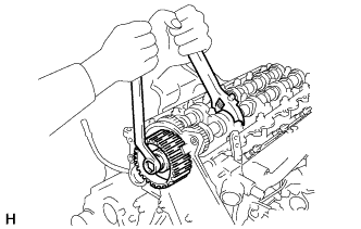
Hold the hexagonal wrench head portion of the camshaft with a wrench, and remove the No.1 camshaft timing pulley bolt.
-
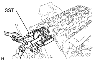
Using SST, remove the No.1 camshaft timing pulley.
- SST
- 09950-40011 ( 09951-04010, 09952-04010, 09953-04020, 09954-04010, 09955-04061 )
-
Remove the set key.
-
-
REMOVE TIMING BELT NO.2 COVER
-
REMOVE EGR PIPE SUB-ASSEMBLY NO.1
-
Remove the 2 nuts.
-
Remove the EGR control valve, EGR pipe sub-assembly and 2 gaskets.
-
-
REMOVE VSV ASSEMBLY
-
Remove the 2 bolts and VSV assembly.
-
-
REMOVE OIL FILTER SUB-ASSEMBLY
-
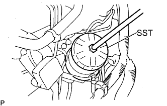
Using SST, remove the oil filter.
- SST
- 09228-10002
Tech Tips
As the oil in the filter flows out through the drain hose, place the drain oil container under the drain hose.
-
Clean the oil filter contact surface on the oil filter mounting.
-
Lubricate the filter rubber gasket with clean engine oil.
-
-
REMOVE INTAKE MANIFOLD
-
Remove the 4 bolts, 2 nuts, intake manifold and gasket.
-
-
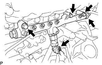
REMOVE FUEL INLET PIPE SUB-ASSEMBLY
-
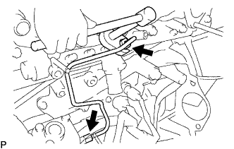
Remove the bolt and injection pipe clamp No. 2.
-
Using a union wrench 17mm, loosen the fuel inlet union of common rail side.
-
Using a union wrench 17 mm, loosen the fuel inlet pipe union of pump side.
-
Remove the inlet pipe sub-assembly.
Note
After removing the fuel pipe, affix the gum tape to the pump, common rail, and the whole injector installation area of the cylinder head cover for preventing dust.
-
-
REMOVE NOZZLE LEAKAGE PIPE ASSEMBLY NO.2
-
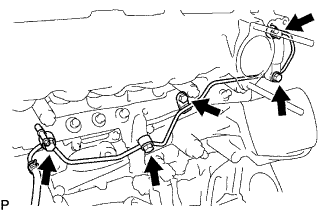
Disconnect the fuel hose from the nozzle leakage pipe assembly No. 2.
-
Remove the 2 bolts, 2 union bolts, check valve, nozzle leakage pipe assembly No. 2 and 3 gaskets.
-
-
REMOVE COMMON RAIL ASSEMBLY
-
Disconnect the sensor connectors.
-
Remove the 3 bolts and common rail assembly.
Note
-
Do not disassemble the pressure limiter.
-
Do not reuse the fuel pressure sensor.
-
-
-
REMOVE CAMSHAFT
-
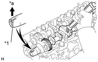
Text in Illustration *1 key Groove *a Upward Set the key groove of the camshaft, facing upward by turning the camshaft with a wrench.
-
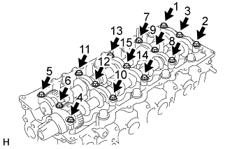
Uniformly loosen and remove the 15 bolts in several passes, in the sequence shown.
-
Remove the 5 camshaft bearing caps.
-
Remove the 2 camshafts and oil seal.
-
-
REMOVE CYLINDER HEAD SUB-ASSEMBLY
-
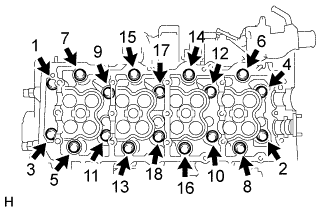
Uniformly loosen and remove the 18 cylinder head bolts, in several passes, in the sequence shown.
Note
Head warpage or cracking could result from removing bolts in incorrect order.
-
Lift the cylinder head from the dowels on the cylinder block, and place the head on wooden blocks on a bench.
Tech Tips
If the cylinder head is difficult to lift off, pry with a screwdriver between the cylinder head and block.
Note
Be careful not to damage the contact surfaces of cylinder head and block.
-
-
REMOVE CYLINDER HEAD GASKET
-
REMOVE SEMICIRCULAR PLUG