VALVE CLEARANCE ADJUSTMENT

Tech Tips
Inspect and adjust the valve clearance when the engine is cold.
Note
-
Before removing the injection pipes, clean them up with a soft brush and compressed air.
-
After removing the injection pipe, affix the gum tape on the supply pump, common rail and the whole injector installation area of the cylinder head cover for preventing dust from coming into them.
-
After removing the cylinder head cover, put a vinyl bag and rubber band for preventing from mixing foreign objects over the injector inlet.
-
REMOVE FRONT SEAT ASSEMBLY RH (W/O TILT CAB CAB TYPE)
-
REMOVE FRONT SEAT ASSEMBLY (DRIVER SEAT) (W/O TILT CAB CAB TYPE)
-
DISCONNECT TRANSMISSION FLOOR SHIFT ASSEMBLY (W/O TILT CAB CAB TYPE)
for G54 Manual Transmission
for R451 Manual Transmission
-
DISCONNECT PARKING BRAKE SHOE LEVER SUB-ASSEMBLY (W/O TILT CAB CAB TYPE)
-
REMOVE ENGINE SERVICE HOLE SUB COVER SUB-ASSEMBLY (W/O TILT CAB CAB TYPE)
-
Remove the front door scuff.
-
Remove the floor mat.
-
Remove the 7 bolts and engine service hole sub-cover.
-
-
REMOVE ENGINE SIDE COVER SUB-ASSEMBLY RH
-
REMOVE ENGINE SIDE COVER SUB-ASSEMBLY LH
-
SET NO. 1 CYLINDER TO TDC / COMPRESSION
-
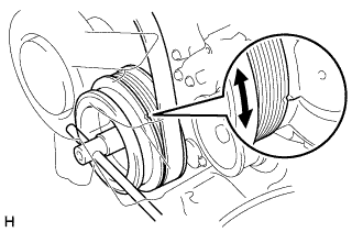
Turn the crankshaft pulley and align its groove with timing pointer.
-
Check that the valve lifters on the No. 1 cylinder are loose and valve lifters on the No. 4 are tight.
If not, turn the crankshaft one revolution (360°) and align the mark as above.
-
-
REMOVE CYLINDER HEAD COVER SUB-ASSEMBLY
-
Disconnect the 4 injector connectors.
-
Remove the 2 bolts and disconnect the engine wire protector.
-
Remove the 4 injection pipes Click here.
-
Remove the 4 nozzle holder seals.
-
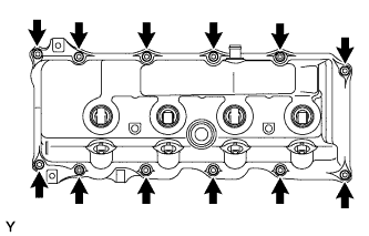
Remove the 10 bolts, 2 nuts, cylinder head cover and the cylinder head cover gasket.
-
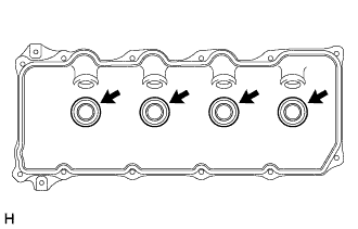
Remove the 4 No. 3 cylinder head cover gaskets from the cylinder head cover.
-
-
REMOVE INJECTOR ASSEMBLY
-
INSPECT VALVE CLEARANCE
-
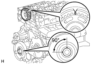
Turn the crankshaft so that the cam lobe of the camshaft on the inspecting valve points upward.
-
Align the timing mark of the camshaft timing pulley with the arrow mark of the timing belt No. 2 cover.
-
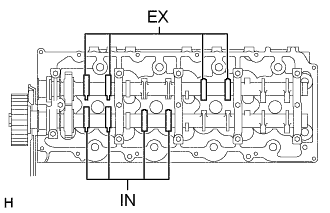
Check only the valves indicated.
-
Using a feeler gauge, measure the clearance between the valve lifter and camshaft.
-
Measure the clearance at 16 places.
-
Record the out-of-specification valve clearance measurements. They will be used later to determine the required replacement adjusting shim.
Valve clearance (Cold) Intake 0.20 - 0.30 mm (0.0079 - 0.0118 in.) Exhaust 0.35 - 0.45 mm (0.0138 - 0.0177 in.)
-
-
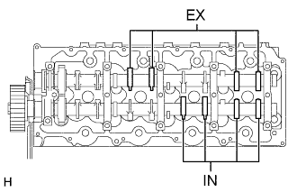
Turn the camshaft 1/2 revolutions (180°).
-
Check only the valves indicated as shown. Measure the valve clearance (See procedure in step (c) above).
-
-
ADJUST VALVE CLEARANCE
-
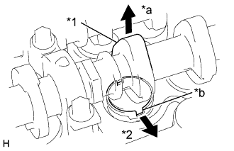
Text in Illustration *1 Cam Lobe *2 Spark Plug Side *a Upward *b Notch Remove the adjusting shim.
-
Turn the crankshaft so that the cam lobe of the camshaft on the adjusting valve points upward.
-
Position the notch of the valve lifter facing the intake manifold side.
-
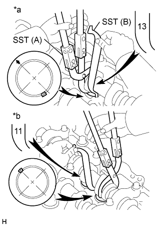
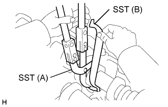
Text in Illustration *a Camshaft Bearing Cap Side *b Other Side Using SST (A), press down the valve lifter and place SST (B) between the camshaft and valve lifter. Remove SST (A).
- SST
- 09248-55050 ( 09248-05510, 09248-05520 )
Tech Tips
-
Camshaft Bearing Cap Side:
Apply SST (B) on the side marked with"13", at the position shown in the illustration.
-
Other Side:
Apply SST (B) on the side marked with"11", at the position shown in the illustration.
-
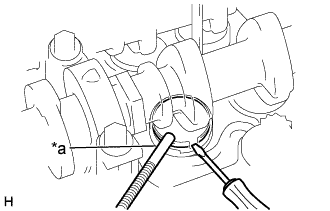
Text in Illustration *a Magnetic Finger Remove the adjusting shim with a small screwdriver and magnetic finger.
-
-
Determine the replacement adjusting shim size by following the Formula or Charts:
-
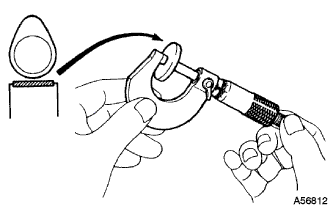
Using a micrometer, measure the thickness of the removed shim.
-
Calculate the thickness of a new shim so that the valve clearance comes within specified value.
T = Thickness of removed shim
A = Measured valve clearance
N = Thickness of new shim
Intake N = T + (A - 0.25 mm (0.010 in.)) Exhaust N = T + (A - 0.45 mm (0.018 in.)) -
Select a new shim with a thickness as close as possible to the calculated value.
Tech Tips
Shims are available in 32 sizes in increments of 0.025 mm (0.0010 in.), from 2.525 mm (0.0994 in.) to 3.300 mm (0.1299 in.).
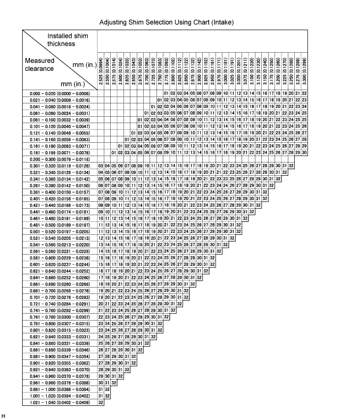
Intake valve clearance (Cold) 0.20 - 0.30 mm (0.0079 - 0.0118 in.) EXAMPLE The 2.800 mm (0.1102 in.) shim is installed, and the measured clearance is 0.350mm (0.0138 in.). Replace the 2.800 mm (0.1102 in.) shim with a new No. 16 shim. New shim thickness mm (in.) No. Shim mark Thickness No. Shim mark Thickness 01 2525 2.525 (0.0994) 17 2925 2.925 (0.1152) 02 2550 2.550 (0.1004) 18 2950 2.950 (0.1161) 03 2575 2.575 (0.1014) 19 2975 2.975 (0.1171) 04 2600 2.600 (0.1024) 20 3000 3.000 (0.1181) 05 2625 2.625 (0.1033) 21 3025 3.025 (0.1191) 06 2650 2.625 (0.1033) 22 3050 3.050 (0.1201) 07 2675 2.675 (0.1053) 23 3075 3.075 (0.1211) 08 2700 2.700 (0.1063) 24 3100 3.100 (0.1220) 09 2725 2.725 (0.1073) 25 3125 3.125 (0.1230) 10 2750 2.750 (0.1083) 26 3150 3.150 (0.1240) 11 2775 2.775 (0.1093) 27 3175 3.175 (0.1250) 12 2800 2.800 (0.1102) 28 3200 3.200 (0.1260) 13 2825 2.825 (0.1112) 29 3225 3.225 (0.1270) 14 2850 2.850 (0.1122) 30 3250 3.250 (0.1280) 15 2875 2.875 (0.1132) 31 3275 3.275 (0.1289) 16 2900 2.900 (0.1142) 32 3300 3.300 (0.1299) 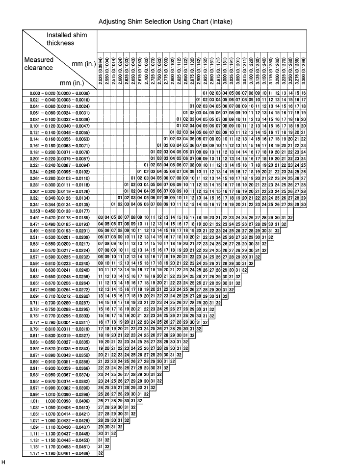
Exhaust valve clearance (Cold) 0.35 - 0.45 mm (0.0138 - 0.0177 in.) EXAMPLE The 2.800mm(0.1102 in.) shim is installed and the measured is 0.350 mm (0.0138 in.). Replace the 2.800 mm (0.1102 in.) shim with a No. 11 shim. The 2.800 mm (0.1102 in.) shim is installed, and the measured clearance is 0.500mm (0.0197 in.). Replace the 2.800 mm (0.1102 in.) shim with a new No. 16 shim. New shim thickness mm (in.) No. Shim mark Thickness No. Shim mark Thickness 01 2525 2.525 (0.0994) 17 2925 2.925 (0.1152) 02 2550 2.550 (0.1004) 18 2950 2.950 (0.1161) 03 2575 2.575 (0.1014) 19 2975 2.975 (0.1171) 04 2600 2.600 (0.1024) 20 3000 3.000 (0.1181) 05 2625 2.625 (0.1033) 21 3025 3.025 (0.1191) 06 2650 2.625 (0.1033) 22 3050 3.050 (0.1201) 07 2675 2.675 (0.1053) 23 3075 3.075 (0.1211) 08 2700 2.700 (0.1063) 24 3100 3.100 (0.1220) 09 2725 2.725 (0.1073) 25 3125 3.125 (0.1230) 10 2750 2.750 (0.1083) 26 3150 3.150 (0.1240) 11 2775 2.775 (0.1093) 27 3175 3.175 (0.1250) 12 2800 2.800 (0.1102) 28 3200 3.200 (0.1260) 13 2825 2.825 (0.1112) 29 3225 3.225 (0.1270) 14 2850 2.850 (0.1122) 30 3250 3.250 (0.1280) 15 2875 2.875 (0.1132) 31 3275 3.275 (0.1289) 16 2900 2.900 (0.1142) 32 3300 3.300 (0.1299)
-
-
Install a new adjusting shim.
-
Place a new adjusting shim on the valve lifter.
-
Using SST (A), press down the valve lifter and remove SST (B).
- SST
- 09248-55050 ( 09248-05510, 09248-05520 )
-
-
Recheck the valve clearance.
-
-
INSTALL INJECTOR ASSEMBLY
-
INSTALL CYLINDER HEAD COVER SUB-ASSEMBLY
-
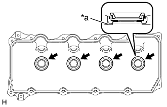
Text in Illustration *a Upper Side of Cylinder Head Cover Install 4 new No. 3 cylinder head cover gaskets to the cylinder head cover as shown in the illustration.
Note
-
Do not install the gaskets at an angle.
-
Keep the lip of the gasket free from foreign materials.
-
-
Install a new cylinder head cover gasket to the cylinder head cover.
-
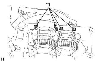
Text in Illustration *1 FIPG Remove any old packing (FIPG) material.
-
Apply seal packing to the cylinder head shown the illustration.
Seal packing Toyota Genuine Seal Packing Black, Three Bond 1207B or equivalent -
Install the cylinder head cover with the 10 bolts and 2 nuts.
- Torque:
- 9.0 N*m { 92 kgf*cm, 78 in.*lbf }
-
Install the 4 nozzle holder seals.
-
Install the 4 injection pipes Click here.
-
Connect the engine wire protector and install the 2 bolts.
-
Connect the 4 injector connectors.
-
-
INSTALL ENGINE SIDE COVER SUB-ASSEMBLY LH
-
INSTALL ENGINE SIDE COVER SUB-ASSEMBLY RH
-
INSTALL ENGINE SERVICE HOLE SUB COVER SUB-ASSEMBLY (W/O TILT CAB CAB TYPE)
- Torque:
- 11.5 N*m { 115 kgf*cm, 8.5 ft.*lbf }
-
INSTALL PARKING BRAKE SHOE LEVER SUB-ASSEMBLY (W/O TILT CAB CAB TYPE)
-
INSTALL TRANSMISSION FLOOR SHIFT ASSEMBLY (W/O TILT CAB CAB TYPE)
for G54 Manual Transmission
for R451 Manual Transmission
-
INSTALL FRONT SEAT ASSEMBLY (DRIVER SEAT) (W/O TILT CAB CAB TYPE)
-
INSTALL FRONT SEAT ASSEMBLY RH (W/O TILT CAB CAB TYPE)