ENGINE UNIT (w/ DPF) INSPECTION
-
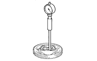
INSPECT NO. 1 IDLE GEAR OIL CLEARANCE
-
Using a cylinder gauge, measure the inside diameter of the idle gear.
Standard idle gear inside diameter 44.000 to 44.025 mm (1.7323 to 1.7333 in.) -
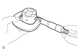
Using a micrometer, measure the diameter of the idle gear shaft.
Standard idle gear shaft diameter 43.955 to 43.990 mm (1.7305 to 1.7319 in.) -
Subtract the idle gear shaft diameter measurement from the idle gear inside diameter measurement.
Standard oil clearance 0.010 to 0.070 mm (0.0004 to 0.0028 in.) Maximum oil clearance 0.20 mm (0.0079 in.) If the clearance is greater than the maximum, replace the gear and shaft.
-
-
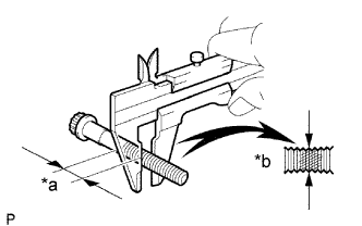
INSPECT CYLINDER HEAD SET BOLT
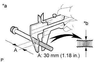
Text in Illustration *a Measuring Point *b Compressed Thread
-
Using a vernier caliper, measure the minimum outside diameter of the compressed thread at the measuring point A.
Standard outside diameter 11.76 to 11.97 mm (0.463 to 0.471 in.) Minimum outside diameter 11.6 mm (0.457 in.) If the outside diameter is less than the minimum, replace the bolt.
-
-
INSPECT CYLINDER BLOCK OIL ORIFICE
-
Check the oil orifice for damage or clogging.
If necessary, replace the oil orifice.
-
-
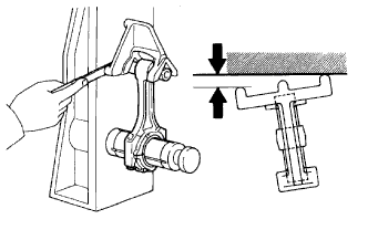
INSPECT OIL CHECK VALVE SUB-ASSEMBLY
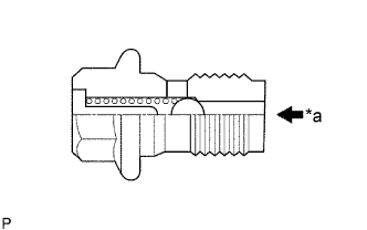
Text in Illustration *a Push
-
Push the valve with a wooden stick to check if it is stuck.
If stuck, replace the check valve.
-
-
INSPECT NO. 1 OIL NOZZLE SUB-ASSEMBLY
-
Check the oil nozzles for damage or clogging.
If necessary, replace the oil nozzle.
-
-
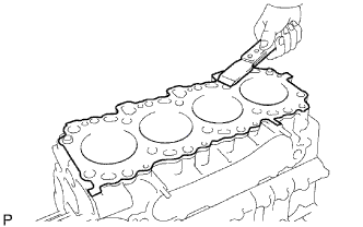
CLEAN CYLINDER BLOCK SUB-ASSEMBLY
-
Using a gasket scraper, remove all the gasket material from the top surface of the cylinder block.
-
Using a soft brush and solvent, thoroughly clean the cylinder block.
-
-
INSPECT CYLINDER BLOCK SUB-ASSEMBLY
-
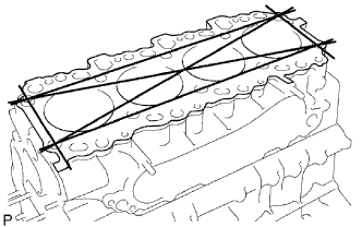
Inspect for flatness.
-
Using a precision straightedge and feeler gauge, measure the surface, which contacts the cylinder head cap, for warpage.
Maximum warpage 0.10 mm (0.0039 in.) If warpage is greater than the maximum, replace the cylinder block.
-
-
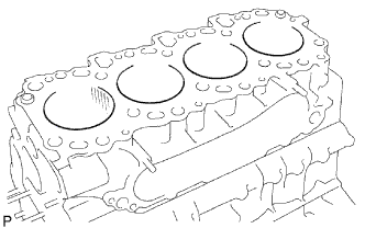
Visually check the cylinder for vertical scratches.
If deep scratches are present, rebore all 4 cylinders. If necessary, replace the cylinder block.
-
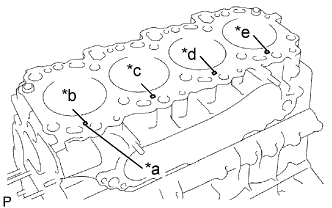
Text in Illustration *a Mark 1, 2 or 3 *b No. 1 *c No. 2 *d No. 3 *e No. 4 Inspect the cylinder bore diameter.
Tech Tips
There are 3 sizes of the standard cylinder bore diameter, marked 1, 2 and 3 accordingly. The mark is stamped on the lower left rear of the cylinder block.
-
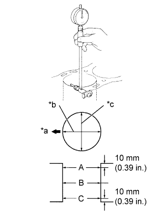
Text in Illustration *a Front *b Thrust Direction *c Axial Direction Using a cylinder gauge, measure the cylinder bore diameter at positions A, B and C in the thrust and axial directions.
Standard Diameter Mark 1 Mark 2 Mark 3 96.000 to 96.010 mm (3.7795 to 3.7799 in.) 96.010 to 96.020 mm (3.7799 to 3.7803 in.) 96.020 to 96.030 mm (3.7803 to 3.7807 in.) Maximum Diameter STD O/S 0.50 O/S 0.75 O/S 1.00 96.23 mm
(3.7886 in.)
96.73 mm
(3.8082 in.)
96.98 mm
(3.8181 in.)
97.23 mm
(3.8279 in.)
If the diameter is greater than the maximum, rebore all 4 cylinders. If necessary, replace the cylinder block.
-
-
-
CLEAN PISTON
-
Using a gasket scraper, remove the carbon from the piston top.
-
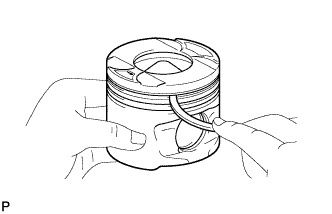
Using a groove cleaning tool or broken ring, clean the piston ring grooves.
-
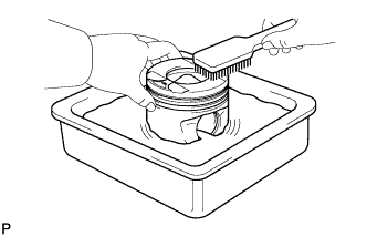
Using solvent and a brush, thoroughly clean the piston.
Note
Do not use a wire brush.
-
-
INSPECT WITH PISTON SUB-ASSEMBLY
Tech Tips
When replacing the piston sub-assembly (w/ pin) with a supply part, there are a number of piston diameter sizes to choose from, but there is only one size of piston pin diameter.
-
Inspect the piston oil clearance.
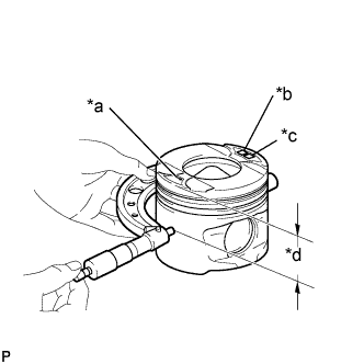
Text in Illustration *a Front Mark (Arrow) *b Size mark *c Piston Pin Inside Diameter Mark *d Distance Tech Tips
There are 3 sizes of the standard piston diameter, marked "1", "2" and "3" accordingly. The mark is stamped on the piston top.
-
Using a micrometer, measure the piston diameter at right angles to the piston center line, at the indicated distance from the piston head.
Standard distance 63.63 mm (2.5051 in.) Standard Piston Diameter Piston Mark Diameter STD Mark 1 95.92 to 95.93 mm (3.77637 to 3.77676 in.) STD Mark 2 95.93 to 95.94 mm (3.77676 to 3.77715 in.) STD Mark 3 95.94 to 95.95 mm (3.77716 to 3.77755 in.) O/S 0.50 - 96.42 to 96.45 mm (3.7960 to 3.7972 in.) O/S 0.75 - 96.67 to 96.70 mm (3.8058 to 3.8071 in.) O/S 1.00 - 96.92 to 96.95 mm (3.8157 to 3.8169 in.) -
Measure the cylinder bore diameter in the thrust direction.
-
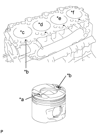
Text in Illustration *a Front Mark *b Mark 1, 2 or 3 *c No. 1 *d No. 2 *e No. 3 *f No. 4 Subtract the piston diameter measurement from the cylinder bore diameter measurement.
Standard oil clearance 0.070 to 0.090 mm (0.0028 to 0.0035 in.) Maximum oil clearance 0.14 mm (0.0055 in.) If the oil clearance is greater than the maximum, replace all 4 pistons and rebore all 4 cylinders.
If necessary, replace the cylinder block.
Tech Tips
Use a piston with the same number mark as the cylinder diameter marked on the cylinder block.
-
-
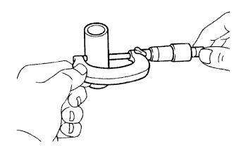
Using a micrometer, measure the piston pin diameter.
Standard Piston Pin Diameter Mark Diameter A 34.000 to 34.004 mm
(1.3386 to 1.3387 in.)
B 34.004 to 34.008 mm
(1.3387 to 1.3389 in.)
C 34.008 to 34.012 mm
(1.3389 to 1.3391 in.)
-
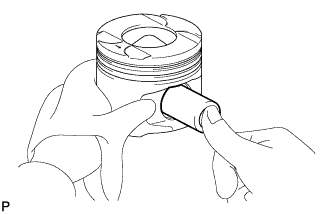
Inspect the piston pin fit.
-
Gradually heat the piston to approximately, check that the piston pin can be pushed into the piston pin hole with your thumb.
If the pin can be installed at a lower temperature, replace the piston and pin as a set.
-
-
-
INSPECT PISTON RING SET
-
Inspect the piston ring groove clearance.
-
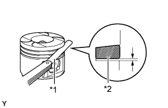
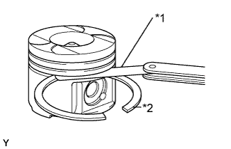
Text in Illustration *1 Feeler Gauge *2 New Piston Ring No. 1 ring:
Install a new No. 1 piston ring to the piston. Using a feeler gauge, measure the clearance between the new piston ring and the wall of the ring groove.
Ring groove clearance (No. 1) 0.091 to 0.135 mm (0.0036 to 0.0053 in.) If the clearance is greater than the maximum, replace the piston.
-
Text in Illustration *1 Feeler Gauge *2 New Piston Ring No. 2 and oil ring:
Using a feeler gauge, measure the clearance between the new piston ring and the wall of the ring groove.
Ring Groove Clearance (No. 2 and Oil Ring) Ring Specification No. 2 0.090 to 0.135 mm (0.0036 to 0.0053 in.) Oil Ring 0.030 to 0.075 mm (0.0012 to 0.0030 in.) If the clearance is greater than the maximum, replace the piston.
-
-
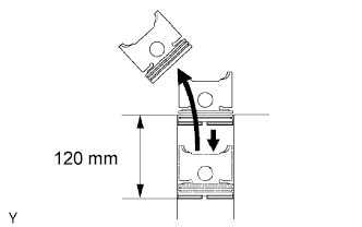
Inspect the piston ring end gap.
-
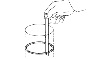
Insert the piston ring into the cylinder bore.
-
Using a piston, push the piston ring a little beyond the bottom of the ring travel and 120 mm (4.72 in.) from the top of the cylinder block.
-
Using a feeler gauge, measure the end gap.
Standard End Gap Ring Specification No. 1 0.27 to 0.39 mm
(0.0106 to 0.0154 in.)
No. 2 0.55 to 0.70 mm
(0.0217 to 0.0276 in.)
Oil 0.20 to 0.40 mm
(0.0079 to 0.0157 in.)
Maximum End Gap Ring Specification No. 1 0.85 mm (0.0335 in.) No. 2 1.07 mm (0.0421 in.) Oil 0.77 mm (0.0303 in.) If the end gap is greater than the maximum, replace the piston ring.
If the end gap is greater than the maximum, even with a new piston ring, rebore all the 4 cylinders or replace the cylinder block.
-
-
-
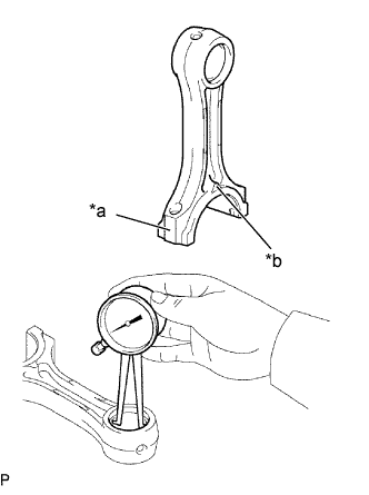
INSPECT CONNECTING ROD SUB-ASSEMBLY
-
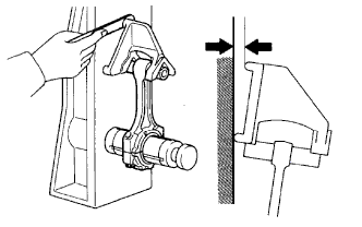
Using a rod aligner and feeler gauge, check the connecting rod alignment.
-
Check if the rod is bent.
Maximum bend 0.03 mm (0.0012 in.) per 100 mm (3.94 in.) If result is greater than the maximum, replace the connecting rod sub-assembly.
-
Check if the rod is twisted.
Maximum twist 0.15 mm (0.0059 in.) per 100 mm (3.94 in.) If result is greater than the maximum, replace the connecting rod sub-assembly.
-
-
-
INSPECT PISTON PIN OIL CLEARANCE
-
Inspect the piston pin oil clearance.
-
Text in Illustration *a Connecting Rod Bush Inside Diameter Mark A, B or C *b Front Mark Using a caliper gauge, measure the inside diameter of the connecting rod bush.
Standard Bush Inside Diameter Size Mark Diameter A 34.012 to 34.016 mm
(1.3390 to 1.3392 in.)
B 34.016 to 34.020 mm
(1.3392 to 1.3393 in.)
C 34.020 to 34.024 mm
(1.3392 to 1.3395 in.)
-
Subtract the piston pin diameter measurement from the bush inside diameter measurement.
Standard oil clearance 0.008 to 0.016 mm (0.0003 to 0.0006 in.) Maximum oil clearance 0.03 mm (0.012 in.) If the oil clearance is greater than the maximum, replace the bush.
If necessary, replace the piston and piston pin as a set.
-
-
-
INSPECT CONNECTING ROD BOLT
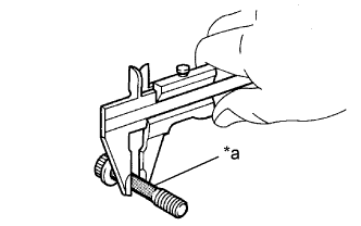
Text in Illustration *a Tension Portion
-
Using a vernier caliper, measure the tension portion of the connecting rod bolt.
Standard diameter 8.500 to 8.600 mm (0.3346 to 0.3385 in.) Minimum diameter 8.30 mm (0.3268 in.) If the diameter is less than the minimum, replace the bolt.
-
-
INSPECT NO. 1 BALANCESHAFT SUB-ASSEMBLY
-
Using a cylinder gauge, measure the inside diameter of the balance shaft bearing.
Text in Illustration *a No. 1 *b No. 2 *c No. 3 Bearing Inside Diameter No. 1 No. 2 No. 3 42.000 to 42.020 mm (1.6535 to 1.6543 in.) 41.000 to 41.020 mm (1.6142 to 1.6150 in.) 32.000 to 32.020 mm (1.2598 to 1.2606 in.) -
Using a micrometer, measure the outside diameter of the balance shaft main journals.
Main Journal Diameter No. 1 No. 2 No. 3 41.941 to 41.960 mm (1.6512 to 1.6520 in.) 40.931 to 40.950 mm (1.6115 to 1.6122 in.) 31.941 to 31.960 mm (1.2575 to 12583 in.) -
Subtract the outside diameter of the balance shaft main journal from the inside diameter to the balance shaft bearing.
Standard Clearance No. 1 No. 2 No. 3 0.040 to 0.079 mm (0.0016 to 0.0031 in.) 0.050 to 0.089 mm (0.0020 to 0.0035 in.) 0.040 to 0.079 mm (0.0016 to 0.0031 in.) Maximum Oil Clearance No. 1 No. 2 No. 3 0.18 mm (0.0071 in.) 0.19 mm (0.0075 in.) 0.18 mm (0.0071 in.) If the clearance is greater than the maximum, replace the cylinder block and balance shaft.
-
-
INSPECT NO. 2 BALANCESHAFT SUB-ASSEMBLY
-
Using a cylinder gauge, measure the inside diameter of the balance shaft bearing.
Text in Illustration *a No. 1 *b No. 2 *c No. 3 Bearing Inside Diameter No. 1 No. 2 No. 3 42.000 to 42.020 mm (1.6535 to 1.6543 in.) 41.000 to 41.020 mm (1.6142 to 1.6150 in.) 32.000 to 32.020 mm (1.2598 to 1.2606 in.) -
Using a micrometer, measure the outside diameter of the balance shaft main journals.
Main Journal Diameter No. 1 No. 2 No. 3 41.941 to 41.960 mm (1.6512 to 1.6520 in.) 40.931 to 40.950 mm (1.6115 to 1.6122 in.) 31.941 to 31.960 mm (1.2575 to 12583 in.) -
Subtract the outside diameter of the balance shaft main journal from the inside diameter to the balance shaft bearing.
Standard Clearance No. 1 No. 2 No. 3 0.040 to 0.079 mm (0.0016 to 0.0031 in.) 0.050 to 0.089 mm 0.0020 to 0.0035 in.) 0.040 to 0.079 mm (0.0016 to 0.0031 in.) Maximum Oil Clearance No. 1 No. 2 No. 3 0.18 mm (0.0071 in.) 0.19 mm (0.0075 in.) 0.18 mm (0.0071 in.) If the clearance is greater than the maximum, replace the cylinder block and balance shaft.
-
-
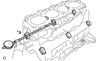
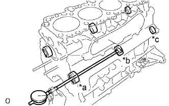
INSPECT CRANKSHAFT
-
Inspect for circle runout.
Text in Illustration *a Center Journal
-
Place the crankshaft on V-blocks.
-
Using a dial indicator, measure the circle runout at the center journal.
Maximum circle runout 0.03 mm (0.0012 in.) If the circle runout is greater than the maximum, replace the crankshaft.
-
-
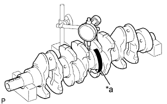
Inspect the main journals and crank pins.
-
Using a micrometer, measure the diameter of each main journal and crank pin.
Standard Main Journal Diameter Mark 1 Mark 2 Mark 3 69.994 to 70.000 mm (2.75566 to 2.75590 in.) 69.988 to 69.994 mm (2.75543 to 2.75566 in.) 69.982 to 69.988 mm (2.75519 to 2.75543 in.) Standard Crank Pin Diameter Mark 1 Mark 2 Mark 3 58.994 to 59.000 mm (2.32259 to 2.32283 in.) 58.988 to 59.994 mm (2.32236 to 2.32259 in.) 58.982 to 58.988 mm (2.32212 to 2.32239 in.) If the diameter is not as specified, check the oil clearance. If necessary, grind or replace the crankshaft.
-
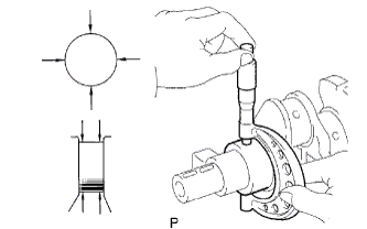
Check each main journal and crank pin for taper and out-of-round as shown.
Maximum taper and out-of-round 0.020 mm (0.0008 in.) If the taper and out-of-round is greater than the maximum, replace the crankshaft.
-
-
If necessary, grind and hone the main journals and/or crank pins.
-
Grind and hone the main journals and/or crank pins to the finished undersized diameter.
-
Install new main journal and/or crankshaft pin undersized bearing.
-
-
-
INSPECT CRANKSHAFT BEARING CAP SET BOLT
Text in Illustration *a Measuring Point *b Elongated Thread
-
Using a vernier caliper, measure the minimum diameter of the compressed thread at the measuring point.
Standard diameter 13.500 to 14.000 mm (0.5315 to 0.5512 in.) Minimum diameter 12.60 mm (0.4961 in.) If the diameter is less than the minimum, replace the bolt.
-