ENGINE UNIT REMOVAL

-
REMOVE ENGINE ASSEMBLY
-
REMOVE VANE PUMP DRIVE PULLEY
-
Remove the 4 bolts, vane pump drive pulley and the vane pump drive pulley spacer.
-
w/ A/C:
Remove the 4 bolts, vane pump drive pulley and the crankshaft pulley No. 2.
-
-
REMOVE CRANKSHAFT PULLEY
-
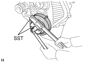
Using SST, remove the pulley bolt.
- SST
- 09213-54015 ( 91651-60855 )
- 09330-00021
-
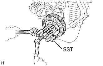
Using SST, remove the pulley.
- SST
- 09213-54015 ( 91651-60855 )
- 09330-00021
- 09950-50013 ( 09951-05010, 09952-05010, 09953-05020, 09954-05021 )
-
-
REMOVE TIMING CHAIN OR BELT COVER SUB-ASSEMBLY
-
Remove the 11 bolts, washers, timing belt cover and 2 gaskets.
-
Remove the collar from the timing pointer.
-
-
REMOVE TIMING BELT
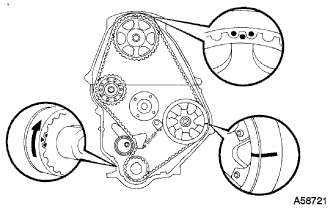
Tech Tips
If re-using the timing belt, draw a direction arrow on the timing belt (in direction of engine revolution), and place matchmarks on the pulleys and timing belt.
-
Remove the timing belt. Click here
-
-
REMOVE INTAKE AIR CONNECTOR SUB-ASSEMBLY
-
Remove the 3 nuts and bolt, intake air connector and gasket.
-
-
REMOVE INTAKE AIR CONNECTOR BRACKET
-
REMOVE OIL FILLER CAP SUB-ASSEMBLY
-
REMOVE CYLINDER HEAD COVER NO.2 (w/ Cylinder Head Cover No.2)
-
Remove the 4 nuts, plate washers and the cylinder head cover.
-
-
REMOVE COMPRESSOR MOUNTING BRACKET NO.1 (W/ AIR CONDITIONER)
-
REMOVE IDLE PULLEY BRACKET (W/ AIR CONDITIONER)
-
REMOVE GENERATOR ASSEMBLY
-
REMOVE FAN BELT ADJUSTING BAR (W/O AIR CONDITIONER)
-
REMOVE INJECTION PIPE CLAMP
-
REMOVE INJECTION PIPE SUB-ASSEMBLY NO.4
-
REMOVE INJECTION PIPE SUB-ASSEMBLY NO.3
-
REMOVE INJECTION PIPE SUB-ASSEMBLY NO.2
-
REMOVE INJECTION PIPE SUB-ASSEMBLY NO.1
-
REMOVE INJECTION PUMP DRIVE PULLEY
-
Using SST, remove the injection pump drive pulley installation nut.
- SST
- 09213-14010 ( 91651-60865 )
- 09330-00021 ( 09330-00030 )
-
Using SST, remove the injection pump drive pulley.
- SST
- 09950-50013 ( 09951-05010, 09952-05010, 09953-05010, 09954-05010 )
Note
The tip and threads of the center bolt 100 should be coated with lubricant.
-
-
REMOVE INJECTION PUMP ASSEMBLY
-
REMOVE ENGINE MOUNTING BRACKET FRONT NO.1 RH
-
REMOVE PUMP BRACKET
-
REMOVE EXHAUST MANIFOLD HEAT INSULATOR NO.1
-
REMOVE ELECTRIC EGR CONTROL VALVE ASSEMBLY (w/EGR)
-
Loosen the union nut holding the EGR valve to the EGR pipe.
-
Remove the 2 bolts, 4 nuts, EGR valve and EGR adapter and gasket.
-
Remove the 2 bolts and EGR pipe.
-
-
REMOVE EXHAUST PIPE ASSEMBLY FRONT
-
Remove the 3 nuts, exhaust pipe and gasket.
-
-
REMOVE EXHAUST MANIFOLD
-
Remove the 6 bolts, 2 nuts, exhaust manifold and gasket.
-
-
REMOVE OIL FILTER SUB-ASSEMBLY
-
Using SST, remove the oil filter.
- SST
- 09228-10002
-
-
REMOVE OIL FILTER BRACKET SUB-ASSEMBLY
-
Remove the union bolt and gasket, and disconnect the vacuum pump oil inlet hose.
-
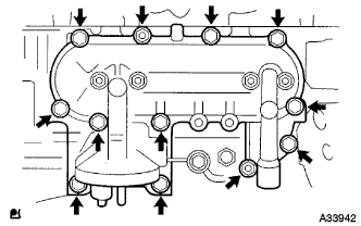
Remove the 10 bolts, 2 nuts, oil filter bracket and gasket.
-
-
REMOVE GLOW PLUG NO.1 CONNECTOR
-
REMOVE GLOW PLUG ASSEMBLY
-
REMOVE NOZZLE LEAKAGE PIPE ASSEMBLY
-
Remove the 4 nuts, nozzle leakage pipe assembly and washer.
-
-
REMOVE NOZZLE HOLDER AND NOZZLE SET
-
Using SST, remove the set of holder and nozzle.
- SST
- 09268-64010 ( 09268-64020 )
-
Remove the nozzle sheet and nozzle sheet gasket.
-
-
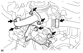
REMOVE WATER OUTLET HOUSING
-
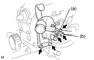
w/ ACSD:
Disconnect the water bypass hose from the water housing.
-
Disconnect the water temperature sender gauge connector.
-
Remove the 3 bolts, the water outlet, outlet housing assembly and gasket.
-
-
REMOVE INTAKE MANIFOLD
-
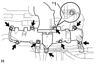
Text in Illustration *1 Oil Dipstick Guide Clamp Remove the bolt and nut, accelerator link and hose clamp (w/ ACSD).
-
Remove the 6 bolts, 2 nuts, 2 engine wire brackets, oil dipstick guide clamp, intake manifold assembly and gasket.
-
-
REMOVE WATER BY-PASS HOSE UNION
-
REMOVE ENGINE COOLANT TEMPERATURE SENSOR
-
REMOVE ENGINE OIL LEVEL SENSOR
-
REMOVE ENGINE OIL PRESSURE SWITCH ASSEMBLY
-
REMOVE VACUUM PUMP INLET UNION
-
REMOVE VACUUM PUMP OUTLET UNION