ENGINE ASSEMBLY INSTALLATION

-
INSTALL FLYWHEEL HOUSING DUST SEAL
-
INSTALL REAR END PLATE
- Torque:
- 18 N*m { 185 kgf*cm, 14 ft.*lbf }
-
INSTALL FLYWHEEL SUB-ASSEMBLY
-
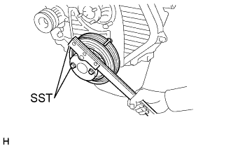
Using SST, fix the crank shaft pulley.
- SST
- 09213-54015 ( 91651-60855 )
- 09330-00021
-
Apply adhesive to 2 or 3 threads of the mounting bolt end.
Adhesive Toyota Genuine Adhesive 1344, Three Bond 1344 or Equivalent -
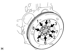
Install the bolts, as shown in the illustration.
- Torque:
- 125.5 N*m { 1250 kgf*cm, 90 ft.*lbf }
Note
Do not start the engine within 1 hour after the installation.
-
-
INSTALL CLUTCH DISC ASSEMBLY
-
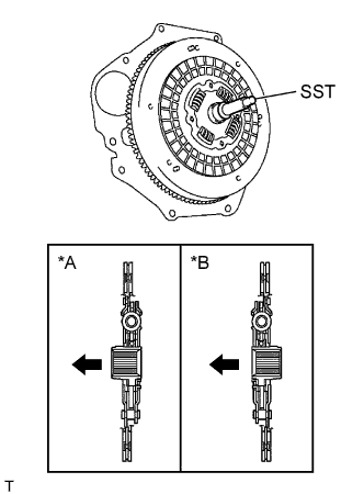
Text in Illustration *A 5L *B 2KD-FTV 
Engine side Insert SST in the clutch disc, then insert them in the flywheel.
- SST
- 09301-00110
Note
Take care not to insert clutch disc in the wrong direction.
-
-
INSTALL CLUTCH COVER ASSEMBLY
-
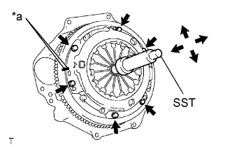
Text in Illustration *a Matchmark Align the matchmarks on the clutch cover and the flywheel.
-
Following the procedures shown in the illustration, tighten the 6 bolts, in the order starting the bolt locating near the knock pin on the top.
- Torque:
- 19.1 N*m { 195 kgf*cm, 14 ft.*lbf }
Tech Tips
-
Following the order in the illustration, tighten the bolts at a time evenly.
-
Move SST up and down, right and left lightly, after checking that the disc is in the center, tighten the bolts.
- SST
- 09301-00110
-
-
INSTALL MANUAL TRANSMISSION UNIT ASSEMBLY
for G54 Manual Transmission
for R451 Manual Transmission
-
INSTALL STARTER ASSEMBLY
for 2.2 kW Type
for 2.7 kW Type
-
INSTALL ENGINE WIRE
-
INSTALL ENGINE W/TRANSMISSION ASSEMBLY
-
Using an engine lifter, install the engine assembly with transmission.
- Torque:
- Engine mounting bracket RH, LH to frame
- 61 N*m { 622 kgf*cm, 45 ft.*lbf }
- Engine mounting bracket RH, LH to engine mounting insulator FR
- 42 N*m { 430 kgf*cm, 31 ft.*lbf }
- Engine mounting bracket RR to engine mounting bracket RR No. 2
- 98 N*m { 1000 kgf*cm, 72 ft.*lbf }
-
Remove the No. 2 engine hanger.
-
-
INSTALL FLOOR SHIFT CABLE TRANSMISSION CONTROL SHIFT
-
Install the control cable with clip and nut.
- Torque:
- 12 N*m { 120 kgf*cm, 9 ft.*lbf }
-
-
INSTALL FLOOR SHIFT CABLE TRANSMISSION CONTROL SELECT
-
Install the control cable with clip and nut.
- Torque:
- 12 N*m { 120 kgf*cm, 9 ft.*lbf }
-
-
INSTALL CLUTCH RELEASE CYLINDER ASSEMBLY
- Torque:
- 11.8 N*m { 11.8 kgf*cm, 9 ft.*lbf }
-
INSTALL PROPELLER SHAFT ASSEMBLY REAR
for 2 Joint Type
for 3 Joint Type
-
INSTALL VANE PUMP ASSEMBLY
-
INSTALL FRONT SUSPENSION MEMBER ASSEMBLY (INDEPENDENT FRONT SUSPENSION)
-
Using an engine lifter, install the front suspension member assembly with the 4 bolts.
- Torque:
- 150 N*m { 1530 kgf*cm, 110 ft.*lbf }
-
Install the front stabilizer cover RH and LH.
- Torque:
- 18 N*m { 185 kgf*cm, 13 ft.*lbf }
-
Install the front shock absorber assembly RH and LH at the lower arm part.
- Torque:
- 105 N*m { 1070 kgf*cm, 77 ft.*lbf }
-
-
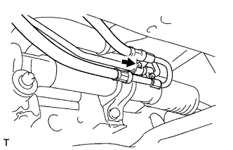
INSTALL PRESSURE FEED TUBE ASSEMBLY (INDEPENDENT FRONT SUSPENSION)
-
Connect the tube with the union bolt and a new gasket.
- Torque:
- 42.1 N*m { 430 kgf*cm, 31 ft.*lbf }
-
-
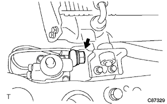
INSTALL STEERING GEAR OUTLET RETURN TUBE (INDEPENDENT FRONT SUSPENSION)
-
Install the return tube.
- Torque:
- 44 N*m { 450 kgf*cm, 33 ft.*lbf }
-
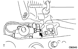
Face the claw to the vehicle is front, and install the return hose to the PS gear assembly with the clip.
-
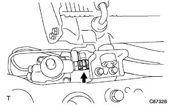
Install the hose with bolt (LHD steering position type only).
- Torque:
- 18 N*m { 184 kgf*cm, 13 ft.*lbf }
-
-
INSTALL STEERING TORQUE SHAFT ASSEMBLY (INDEPENDENT FRONT SUSPENSION)
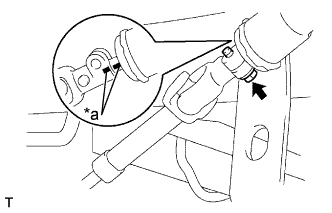
Text in Illustration *a Matchmark
-
Align the matchmarks on the torque shaft and bevel gear.
-
Tighten the bolt.
- Torque:
- 35 N*m { 357 kgf*cm, 26 ft.*lbf }
-
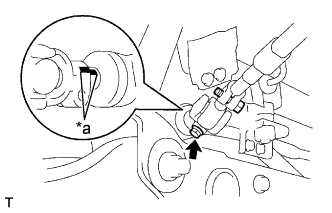
Text in Illustration *a Matchmark Align the matchmarks on the sliding yoke and steering gear.
-
Tighten the bolt.
- Torque:
- 35 N*m { 357 kgf*cm, 26 ft.*lbf }
-
-
INSTALL FRONT SPRING BUMPER NO.1 (INDEPENDENT FRONT SUSPENSION)
- Torque:
- 120 N*m { 1225 kgf*cm, 88 ft.*lbf }
-
INSTALL TIE ROD END SUB-ASSEMBLY LH (INDEPENDENT FRONT SUSPENSION)
-
Connect the tie rod end to the knuckle arm.
-
Install the nuts and new cotter pin.
- Torque:
- 91 N*m { 928 kgf*cm, 67 ft.*lbf }
-
-
INSTALL TIE ROD END SUB-ASSEMBLY RH (INDEPENDENT FRONT SUSPENSION)
Tech Tips
Connect the RH side by the same procedures with the LH side.
-
INSTALL TIE ROD END SUB-ASSEMBLY LH (RIGID FRONT SUSPENSION)
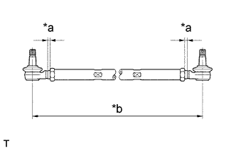
Text in Illustration *a 6.5 mm (0.3 in) *b 1163 mm (45.8 in)
-
Screw the lock nuts and tie rod ends into the tie rod.
Tech Tips
The tie rod length should be approximately 1163 mm (45.8 in.), and the remaining length of threads on both tie rods should be equal.
-
-
INSTALL TIE ROD END SUB-ASSEMBLY RH (RIGID FRONT SUSPENSION)
Tech Tips
Install the RH side by the same procedures with the LH side.
-
INSTALL EXHAUST FRONT PIPE ASSEMBLY NO.2
-
CONNECT ENGINE WIRE
-
INSTALL AIR CLEANER HOSE NO.1
-
INSTALL COMPRESSOR AND MAGNETIC CLUTCH (W/ AIR CONDITIONER)
- Torque:
- 24.5 N*m { 250 kgf*cm, 18 ft.*lbf }
-
INSTALL FUEL RETURN TUBE FUEL HOSE
-
INSTALL MAIN TUBE, NO.1 FUEL HOSE
-
INSTALL THROTTLE CONTROL CABLE SUPPORT
- Torque:
- 19 N*m { 195 kgf*cm, 14 ft.*lbf }
-
INSTALL FAN SHROUD
-
Insert the fan shroud and the fan with coupling simultaneously.
-
Install the fan with coupling with the 4 nuts.
-
Install the fan shroud with the 2 bolts.
- Torque:
- 18.5 N*m { 185 kgf*cm, 14 ft.*lbf }
-
-
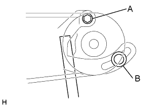
INSTALL FAN AND GENERATOR V BELT
-
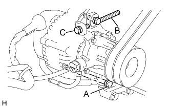
For vehicles with A/C.
-
Install the V belt.
-
Tightening the bolt C, adjust the tension of the V belt.
-
Tighten the bolts A and B.
- Torque:
- Bolt A
- 65 N*m { 650 kgf*cm, 48 ft.*lbf }
- Bolt B
- 18 N*m { 185 kgf*cm, 13 ft.*lbf }
-
Check the tension of the V belt Click here.
-
-
For vehicles without A/C.
-
Install the V belt.
-
Using a bar, adjust the tension of the V belt.
-
Tighten the bolts A and B.
-
Check the tension of the V belt.
- Torque:
- Bolt A
- 65 N*m { 650 kgf*cm, 48 ft.*lbf }
- Bolt B
- 18 N*m { 185 kgf*cm, 13 ft.*lbf }
-
Check the tension of the V belt Click here.
-
-
-
INSTALL V (COOLER COMPRESSOR TO CRANKSHAFT PULLEY) BELT NO.1 (W/ AIR CONDITIONER)
-
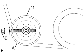
Text in Illustration *1 Idler pulley Install the V belt.
-
Tightening the bolt B, adjust the tension of the V belt.
-
Tighten nut A.
- Torque:
- 39 N*m { 400 kgf*cm, 29 ft.*lbf }
-
Check the tension of the V belt Click here.
-
-
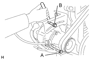
INSTALL VANE PUMP V BELT
-
Install the V belt.
-
Using a bar, adjust the tension of the V-ribbed belt.
-
Tighten the bolts A and B.
- Torque:
- Bolt A
- 72 N*m { 730 kgf*cm, 53 ft.*lbf }
- Bolt B
- 48 N*m { 490 kgf*cm, 35 ft.*lbf }
-
Check the tension of the V belt Click here.
-
-
INSTALL RADIATOR HOSE OUTLET
-
INSTALL HEATER WATER OUTLET HOSE B (W/ HEATER)
-
INSTALL HEATER WATER INLET HOSE A (W/ HEATER)
-
INSTALL RADIATOR HOSE INLET
-
INSTALL ENGINE SERVICE HOLE SUB COVER SUB-ASSEMBLY (W/O TILT CAB CAB TYPE)
- Torque:
- 11.5 N*m { 115 kgf*cm, 8.5 ft.*lbf }
-
INSTALL PARKING BRAKE LEVER ASSEMBLY (W/O TILT CAB CAB TYPE)
-
INSTALL TRANSMISSION FLOOR SHIFT ASSEMBLY (W/O TILT CAB CAB TYPE)
for G54 Manual Transmission
for R451 Manual Transmission
-
INSTALL FRONT SEAT ASSEMBLY (DRIVER SEAT) (W/O TILT CAB CAB TYPE)
-
Temporarily install front side of the front seat assembly RH with the 2 bolts.
-
Install the 2 rear side bolts.
- Torque:
- 39.0 N*m { 398 kgf*cm, 29 ft.*lbf }
-
Tighten the 2 front side bolts.
- Torque:
- 39.0 N*m { 398 kgf*cm, 29 ft.*lbf }
-
Install the seat track cover.
-
-
INSTALL ENGINE UNDER COVER SUB-ASSEMBLY NO.2
-
INSTALL ENGINE UNDER COVER SUB-ASSEMBLY NO.1
-
BLEED INJECTION PIPE
-
REFILL ENGINE COOLANT
-
CHECK ENGINE COOLANT LEAK
-
ADD POWER STEERING FLUID
-
BLEED POWER STEERING FLUID
-
Check the fluid level.
-
Jack up the front of the vehicle and support it with stands.
-
Turn the steering wheel.
-
With the engine stopped, turn the wheel slowly from lock to lock several times.
-
-
Lower the vehicle.
-
Start the engine.
-
Run the engine at idle for a few minutes.
-
-
Turn the steering wheel.
-
With the engine idling, turn the wheel to the left or right full lock position and keep it there for 2 - 3 seconds. Then turn the wheel to the opposite full lock position and keep it there for 2 - 3 seconds (step A).
-
Repeat step A several times.
-
-
Stop the engine.
-
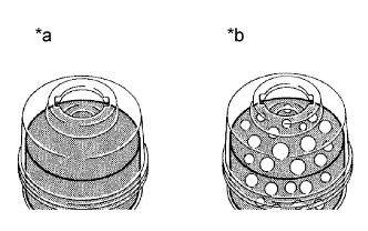
Text in Illustration *a Normal *b Abnormal Check for foaming or emulsification.
Especially, if the system has to be bled twice because of foaming or emulsification, check for fluid leakage in the system.
-
Check the fluid level.
-
-
CHECK POWER STEERING FLUID LEAKAGE
-
INSPECT AND ADJUST FRONT WHEEL ALIGNMENT (INDEPENDENT FRONT SUSPENSION)
-
INSPECT AND ADJUST FRONT WHEEL ALIGNMENT (RIGID FRONT SUSPENSION)