ENGINE ASSEMBLY REMOVAL

-
DISCONNECT BATTERY NEGATIVE TERMINAL
-
DRAIN COOLANT
-
REMOVE ENGINE UNDER COVER SUB-ASSEMBLY NO.1
-
REMOVE ENGINE UNDER COVER SUB-ASSEMBLY NO.2
-
REMOVE FRONT SEAT ASSEMBLY (DRIVER SEAT) (W/O TILT CAB CAB TYPE)
-
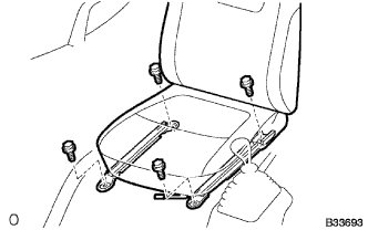
Remove the seat track cover.
-
Remove the 4 bolts.
-
Remove the front seat assembly RH.
-
-
REMOVE TRANSMISSION FLOOR SHIFT ASSEMBLY (W/O TILT CAB CAB TYPE)
for G54 Manual Transmission
for R451 Manual Transmission
-
REMOVE PARKING BRAKE LEVER ASSEMBLY (W/O TILT CAB CAB TYPE)
-
REMOVE ENGINE SERVICE HOLE SUB COVER SUB-ASSEMBLY (W/O TILT CAB CAB TYPE)
-
Remove the front door scuff.
-
Remove the floor mat.
-
Remove the 7 bolts and the engine service hole sub-cover.
-
-
DISCONNECT RADIATOR HOSE INLET
-
REMOVE FAN SHROUD
-
Remove the 2 bolts, and then disconnect the fan shroud.
-
Remove the 4 nuts holding the fan with coupling, and also the fan shroud together with fan with coupling.
-
-
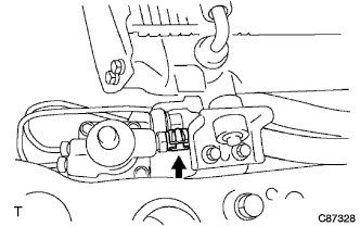
DISCONNECT HEATER WATER INLET HOSE A (W/ HEATER)
-
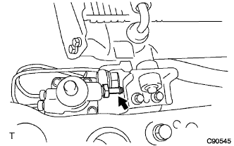
DISCONNECT HEATER WATER OUTLET HOSE B (W/ HEATER)
-
DISCONNECT RADIATOR HOSE OUTLET
-
REMOVE THROTTLE CONTROL CABLE SUPPORT
Tech Tips
Remove the throttle control cable support with the accelerator flexible wire connected.
-
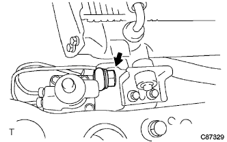
DISCONNECT MAIN TUBE, NO.1 FUEL HOSE
-
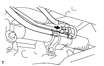
DISCONNECT FUEL RETURN TUBE FUEL HOSE
-
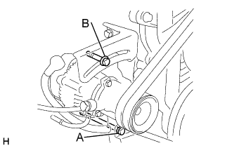
REMOVE VANE PUMP V BELT
-
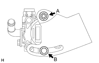
Loosen the nut A and bolt B, and remove the V belt.
-
-
REMOVE V (COOLER COMPRESSOR TO CRANKSHAFT PULLEY) BELT NO.1 (W/ AIR CONDITIONER)
-
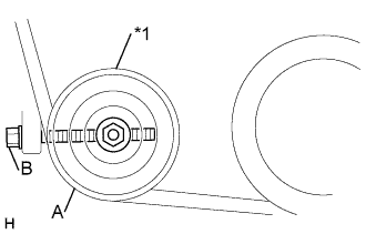
Text in Illustration *1 Idler pulley Loosen the nut A and bolt B, and remove the V belt.
-
-
REMOVE FAN AND GENERATOR V BELT
-
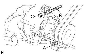
For vehicles with A/C.
-
Loosen the bolts A and B, and remove the V belt.
-
-
For vehicles without A/C.
-
Loosen the bolts A and B, and remove the V belt.
-
-
-
DISCONNECT COMPRESSOR AND MAGNETIC CLUTCH (W/ AIR CONDITIONER)
Tech Tips
Disconnect the compressor and magnetic clutch with the high and low pressure hoses connected, and it should be hung with rope.
-
REMOVE AIR CLEANER HOSE NO.1
-
DISCONNECT ENGINE WIRE
-
REMOVE EXHAUST PIPE ASSEMBLY FRONT NO.2
-
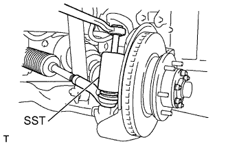
DISCONNECT TIE ROD END SUB-ASSEMBLY LH (INDEPENDENT FRONT SUSPENSION)
-
Remove the cotter pin and nut.
-
Using SST, disconnect the tie rod end from the steering knuckle arm.
- SST
- 09610-20012
-
-
DISCONNECT TIE ROD END SUB-ASSEMBLY RH (INDEPENDENT FRONT SUSPENSION)
Tech Tips
Remove the RH side by the same procedures with the LH side.
-
DISCONNECT TIE ROD END SUB-ASSEMBLY LH (RIGID FRONT SUSPENSION)
-
Loosen the lock nut.
-
Remove the tie rod end and lock nut.
-
-
DISCONNECT TIE ROD END SUB-ASSEMBLY RH (RIGID FRONT SUSPENSION)
Tech Tips
Remove the RH side by the same procedures with the LH side.
-
REMOVE FRONT SPRING BUMPER NO.1 (INDEPENDENT FRONT SUSPENSION)
-
Remove the nut and front spring bumper No.1 RH and LH.
-
-
DISCONNECT STEERING TORQUE SHAFT ASSEMBLY (INDEPENDENT FRONT SUSPENSION)
-
Remove the 3 bolts, steering link protector UPR and steering link protector LWR.
-
Remove the 2 bolts.
-
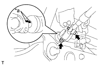
Text in Illustration *a Matchmark Shift the sliding yoke and place the matchmarks to the sliding yoke and steering gear.
-
Remove the bolt.
-
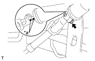
Text in Illustration *a Matchmark Shift the torque shaft and place the matchmarks to the torque shaft and bevel gear.
-
Remove the torque shaft.
-
-
DISCONNECT PRESSURE FEED TUBE ASSEMBLY (INDEPENDENT FRONT SUSPENSION)
-
Remove the union bolt and gasket, and disconnect the feed tube.
-
-
DISCONNECT STEERING GEAR OUTLET RETURN TUBE (INDEPENDENT FRONT SUSPENSION)
-
Remove the bolt (LHD steering position type only).
-
Remove the clip and disconnect the return hose.
-
Remove the return tube.
-
-
REMOVE FRONT SUSPENSION MEMBER ASSEMBLY (INDEPENDENT FRONT SUSPENSION)
-
Remove the front stabilizer cover RH and LH.
-
Disconnect the front shock absorber assembly RH and LH at the lower arm part.
-
Using an engine lifter to hold the front suspension member assembly, remove the 4 bolts.
-
Remove the front stabilizer bar, power steering gear assembly, lower arm RH and LH, and front suspension member assembly all together.
-
-
DISCONNECT VANE PUMP ASSEMBLY
-
REMOVE PROPELLER SHAFT ASSEMBLY REAR
for 2 Joint Type
for 3 Joint Type
-
DISCONNECT CLUTCH RELEASE CYLINDER ASSEMBLY
Tech Tips
Disconnect the clutch release cylinder assembly with the hose connected, and then it should be hung with rope.
-
DISCONNECT FLOOR SHIFT CABLE TRANSMISSION CONTROL SELECT
-
Remove the clip and nut, and then disconnect the select cable from the transmission.
-
-
DISCONNECT FLOOR SHIFT CABLE TRANSMISSION CONTROL SHIFT
-
Remove the clip and nut, and then disconnect the shift cable from the transmission.
-
-
REMOVE ENGINE W/TRANSMISSION ASSEMBLY
-
Using an engine lifter to hold the engine, separate the mount of the transmission.
-
Disconnect the parking brake cable No. 3 (for vehicles with center brake).
-
First remove the engine front mounting bracket RH and LH, and then the engine assembly with transmission.
-
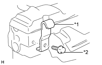
Text in Illustration *1 No. 2 Engine hanger *2 Bolt Install the No. 2 engine hanger in the correct direction.
Part No. No. 2 engine hanger 12282-54060 Bolt 91612-61022 - Torque:
- 37 N*m { 380 kgf*cm, 27 ft.*lbf }
-
Using a chain block and engine sling device, hang up the engine assembly so as not tilt it.
CAUTION:
Do not attempt to hang the engine by hooking the chain to any other part.
-
-
REMOVE ENGINE WIRE
-
REMOVE STARTER ASSEMBLY
for 2.2 kW Type
for 2.7 kW Type
-
REMOVE MANUAL TRANSMISSION UNIT ASSEMBLY
for G54 Manual Transmission
for R451 Manual Transmission
-
REMOVE CLUTCH COVER ASSEMBLY
-
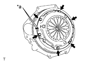
Text in Illustration *a Matchmark Place the matchmarks on the clutch cover with the one on the flywheel.
-
Loosen each set bolt one turn at a time until spring tension is released.
-
Remove the set bolts, and pull off the clutch cover.
Note
Do not drop the clutch disc.
-
-
REMOVE CLUTCH DISC ASSEMBLY
Note
Keep the lining part of the clutch disc assembly, the pressure plate and surface of the flywheel away from oil and foreign attachment.
-
REMOVE FLYWHEEL SUB-ASSEMBLY
-
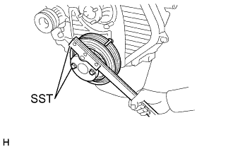
Using SST to fix the crank shaft pulley, remove the fly wheel.
- SST
- 09213-54015 ( 91651-60855 )
- 09330-00021
-
-
REMOVE REAR END PLATE
-
REMOVE FLYWHEEL HOUSING DUST SEAL