CYLINDER BLOCK REASSEMBLY

Tech Tips
-
Thoroughly clean all parts to be assembled.
-
Before installing the parts, apply new engine oil to all sliding and rotating surfaces.
-
Replace all gaskets, O-rings and oil seals with new parts.
-
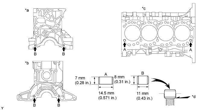
INSTALL TIGHT PLUG
-
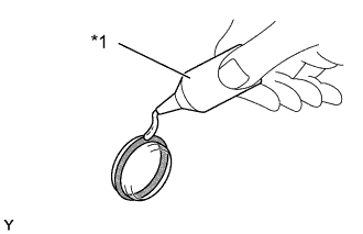
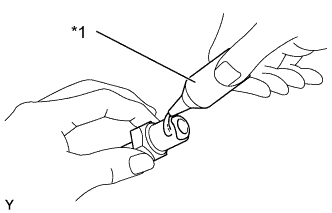
Text in Illustration *1 Adhesive Apply adhesive to a new tight plug.
Adhesive Toyota Genuine Adhesive 1324, Three Bond 1324 or Equivalent -
Using SST and a hammer, tap in the tight plug as shown in the illustration.
Position A:
- SST
- 09950-60010 ( 09951-00250 )
- 09950-70010 ( 09951-07100 )
Position B:
- SST
- 09950-60010 ( 09951-00350 )
- 09950-70010 ( 09951-07100 )
Position C:
- SST
- 09950-60010 ( 09951-00500 )
- 09950-70010 ( 09951-07100 )
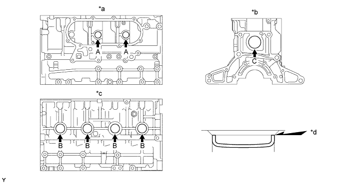
Text in Illustration *a Right Side *b Rear Side *c Left Side *d Stops
-
-
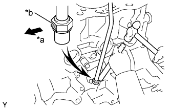
INSTALL STUD BOLT
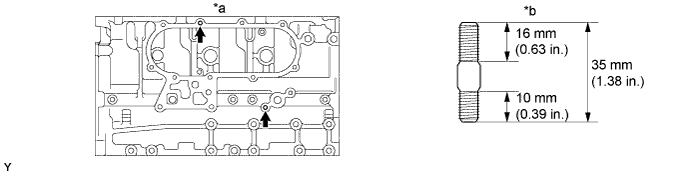
Text in Illustration *a Right Side *b Thread diameter: 8 mm - Torque:
- 14.5 N*m { 150 kgf*cm, 11 ft.*lbf }
-
INSTALL STRAIGHT PIN
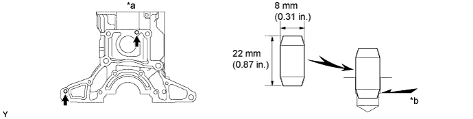
Text in Illustration *a Right Side *b Until pin stops -
INSTALL RING PIN
Text in Illustration *a Rear Side *b Front Side *c Cylinder Head Side *d Until pin stops -
INSTALL OIL LEVEL GAGE GUIDE
-
Text in Illustration *1 Adhesive Apply adhesive to the surface of the guide contacting the cylinder block.
Adhesive Toyota Genuine Adhesive 1324, Three Bond 1324 or Equivalent -
Text in Illustration *a Front *b Painted Mark Using a bass bar and hammer, tap in the hexagon wrench head portion of the level gauge guide with the painted mark facing forward.
-
-
INSTALL W/HEAD TAPER SCREW PLUG NO.1
-
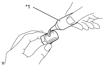
Text in Illustration *1 Adhesive Apply adhesive to 2 or 3 threads.
Adhesive Toyota Genuine Adhesive 1324, Three Bond 1324 or Equivalent -
Install the screw plug.
- Torque:
- 19.5 N*m { 200 kgf*cm, 14 ft.*lbf }
-
-
INSTALL CYLINDER BLOCK WATER DRAIN COCK SUB-ASSEMBLY
-
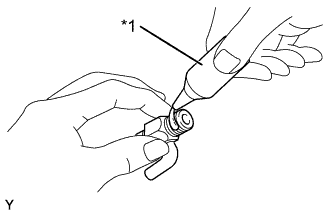
Text in Illustration *1 Adhesive Apply adhesive to 2 or 3 threads.
Adhesive Toyota Genuine Adhesive 1324, Three Bond 1324 or Equivalent -
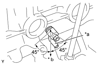
Text in Illustration *a Port *b Downward Install the drain union.
- Torque:
- 49 N*m { 500 kgf*cm, 36 ft.*lbf }
Tech Tips
-
After applying the specified torque, rotate the drain union clockwise until its drain port is facing downward.
-
The drain port may be set within 45° of either side of the prescribed position.
-
-
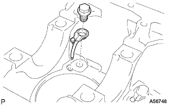
INSTALL CYLINDER BLOCK OIL ORIFICE
-
Using a 6 mm hexagon wrench, install the oil orifice.
- Torque:
- Reference
- 11 N*m { 110 kgf*cm, 8 ft.*lbf }
-
-
INSTALL SUB-ASSEMBLY OIL NOZZLE NO. 1
-
Align the pin of the oil nozzle with the pin hole of the cylinder block.
-
Install the oil nozzle with the check valve. Install the 4 oil nozzles and check valves.
- Torque:
- 25 N*m { 260 kgf*cm, 18 ft.*lbf }
-
-
INSTALL CONNECTING ROD SMALL END BUSH
-
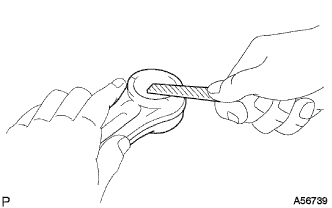
Using a round file, lightly file off any roughness from the small end of the connecting rod.
-
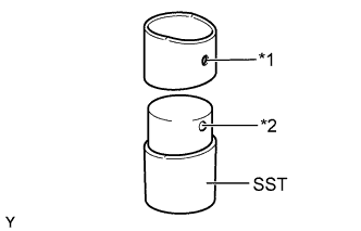
Text in Illustration *1 Oil Hole *2 Ball Attach a new bush to SST with the ball of SST inside the oil hole of the bush.
- SST
- 09222-54011 ( 09222-03021 )
-
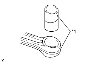
Text in Illustration *1 Oil Hole Align the oil holes of the bush and connecting rod.
-
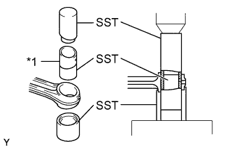
Text in Illustration *1 Bushing Using SST and a press, press in the bush.
- SST
- 09222-54011 ( 09222-03016, 09222-03021, 09222-03026 )
-
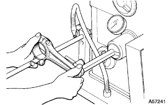
Using a pin hole grinder, hone the bush to obtain the standard specified clearance (See step Click here) between the bush and piston pin.
-
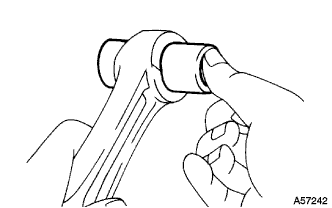
Check the piston pin fit at normal room temperature. Coat the piston pin with engine oil, and push it into the connecting rod with your thumb.
-
-
INSTALL W/PIN PISTON SUB-ASSEMBLY
-
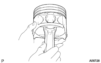
Assemble the piston and connecting rod.
-
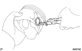
Using snap ring pliers, install a new snap ring on one side of the piston pin hole.
-
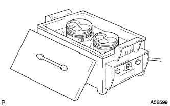
Gradually heat the piston to about 60°C (140°F).
-
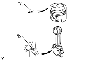
Text in Illustration *a Front Mark (Arrow) *b Front Mark (Protrusion) Coat the piston pin with engine oil.
-
Align the front marks of the piston and connecting rod, and push in the piston pin with your thumb.
-
Check fit between the piston and piston pin.
-
Try to move the piston back and forth on the piston pin.
-
-
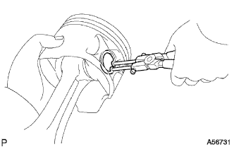
Using snap ring pliers, install a new snap ring on the other side of the piston pin hole.
-
-
Text in Illustration *1 Oil Ring Ends *2 Coil Joint Install the piston rings.
-
Install the coil and oil ring by hand.
Tech Tips
Face the end gap of the oil ring in the opposite direction coil joint.
-
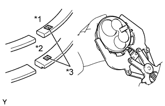
Text in Illustration *1 No. 1 *2 No. 2 *3 Code Mark Using a piston ring expander, install the No. 1 and No. 2 piston rings with the code mark facing upward.
Code mark No. 1 1N No. 2 2N -
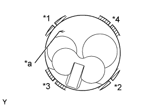
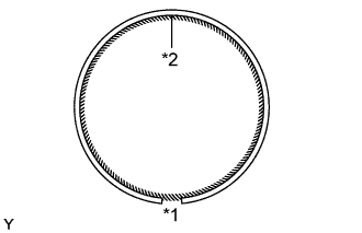
Text in Illustration *1 Oil Ring *2 Coil *3 No.1 Ring *4 No.2 Ring *a Front Mark (Arrow) Position the piston rings so that the ring ends are as shown.
Note
Do not align the ring ends.
-
-
-
INSTALL CONNECTING ROD BEARING
-
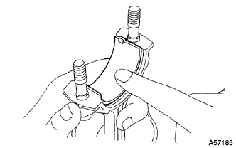
Align the bearing claw with the groove of the connecting rod or connecting cap.
-
Install the bearings in the connecting rod and connecting rod cap.
-
-
INSTALL CRANKSHAFT BEARING
Tech Tips
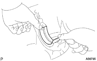
Upper bearings have an oil groove and oil hole; lower bearings do not.
-
Align the bearing claw with the claw groove of the cylinder block, and push in the 5 upper bearings.
-
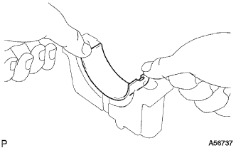
Align the bearing claw with the claw groove of the crankshaft bearing cap, and push in the 5 lower bearings.
-
-
INSTALL CRANKSHAFT THRUST WASHER SET
-
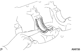
Install the 2 thrust washers under the No. 3 journal position of the cylinder block with the oil grooves facing outward.
-
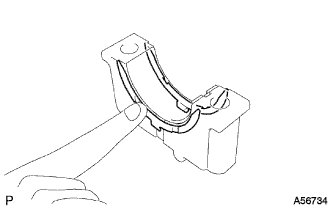
Install the 2 thrust washers on the No. 3 crankshaft bearing cap with the grooves facing outward.
-
-
INSTALL CRANKSHAFT
-
Place the crankshaft on the cylinder block.
-
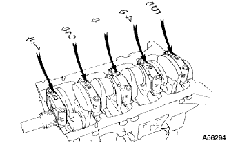
Install the 5 crankshaft bearing caps in their proper locations.
-
Install the crankshaft bearing cap bolts.
-
Apply a light coat of the engine oil on the threads and under the bolt heads of the crankshaft bearing caps.
-
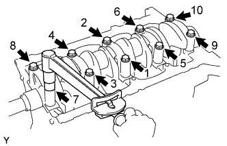
Install and uniformly tighten the 10 bolts of the crankshaft bearing caps, in several passes, in the sequence shown.
- Torque:
- 105 N*m { 1050 kgf*cm, 77 ft.*lbf }
-
-
Check that the crankshaft turns smoothly.
-
Check the crankshaft thrust clearance (See step Click here).
-
-
INSTALL PISTON AND CONNECTING ROD
-
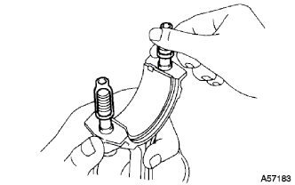
Cover the connecting rod bolts with a short piece of hose to protect the crankshaft and cylinder bore from damage.
-
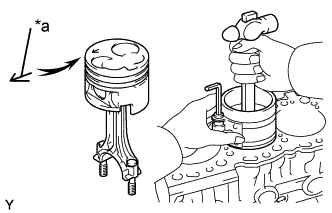
Text in Illustration *a Front Mark (Arrow) Using a piston ring compressor, push the correctly numbered piston and connecting rod assembly into the cylinder with the front mark of the piston facing forward.
-
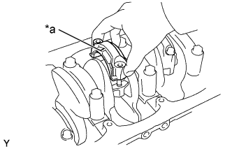
Text in Illustration *a Front Mark (Protrusion) Place the connecting rod cap on the connecting rod.
-
Match the numbered connecting rod cap with the connecting rod.
-
Install the connection rod cap with the front mark facing forward.
-
-
Install the connecting rod cap nuts.
Tech Tips
-
The connecting rod cap nuts are tightened in 2 progressive steps (steps (2) and (4)).
-
If any connecting rod bolt is broken or deformed, replace it.
-
Apply a light of engine oil on the threads and under the heads of the connecting rod cap nuts.
-
Install and alternately tighten the nuts of the connecting rod cap in several passes.
- Torque:
- 54 N*m { 550 kgf*cm, 40 ft.*lbf }
If any one of the connecting rod cap nuts does not meet the torque specification, replace the cap nuts.
-
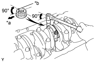
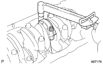
Text in Illustration *a Front *b Painted Mark Mark the front of the connecting rod cap nuts with paint.
-
Retighten the connecting rod cap nuts 90° as shown.
-
Check that the painted mark is now at a 90° angle to the front.
-
-
Check that the crankshaft turns smoothly.
-
Check the connecting rod thrust clearance (See step Click here).
-