CYLINDER BLOCK DISASSEMBLY

Tech Tips
-
Thoroughly clean all parts to be assembled.
-
Before installing the parts, apply new engine oil to all sliding and rotating surfaces.
-
Replace all gaskets, O-rings and oil seals with new parts.
-
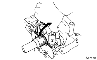
INSPECT CONNECTING ROD THRUST CLEARANCE
-
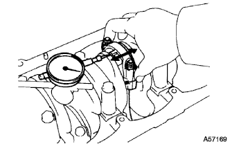
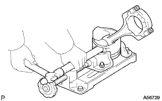
Using a dial indicator, measure the thrust clearance while moving the connecting rod back and forth.
Standard thrust clearance 0.080 - 0.300 mm (0.0031 - 0.0118 in.) Maximum thrust clearance 0.35 mm (0.0138 in.) If the thrust clearance is greater than maximum, replace the connecting rod assembly. If necessary, replace the crankshaft.
-
-
INSPECT CONNECTING ROD OIL CLEARANCE
-
Check the matchmarks on the connecting rod and cap to ensure correct reassembly.
-
Remove the 2 connecting rod cap nuts.
-
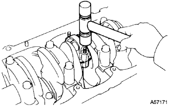
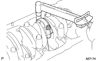
Using a plastic-faced hammer, lightly tap the connecting rod bolts and lift off the connecting rod cap.
Tech Tips
Keep the lower bearing inserted with the connecting rod cap.
-
Cover the connecting rod bolts with a short piece of hose to protect the crankshaft from damage.
-
Clean the crank pin and bearing.
-
Check the crank pin and bearing for pitting and scratches.
If the crank pin or bearing is damaged, replace the bearings. If necessary, grind or replace the crankshaft.
-
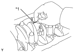
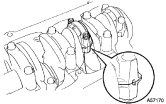
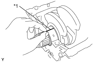
Text in Illustration *1 Plastigage Lay a strip of Plastigage across the crank pin.
-
Install the connecting rod cap with the 2 nuts (See step Click here).
Note
Do not turn the crankshaft.
-
Remove the 2 nuts, connecting rod cap and lower bearing (See procedure (b) and (c) above).
-
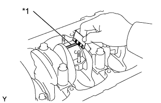
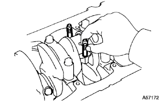
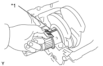
Text in Illustration *1 Plastigage 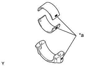
Text in Illustration *a Mark 1, 2 or 3 Measure the Plastigage at its widest point.
Standard oil clearance STD 0.036 - 0.064 mm (0.0014 - 0.0025 in.) U/S 0.25, U/S 0.50 0.033 - 0.079 mm (0.0013 - 0.0031 in.) Maximum oil clearance 0.10 mm (0.0039 in.) If the oil clearance is greater than maximum, replace the bearings. If necessary, grind or replace the crankshaft.
Tech Tips
If using a standard bearing, replace it with one having the same number marked on the connecting rod cap. There are 3 sizes of standard bearings, marked 1, 2 and 3 accordingly.
Standard sized bearing center wall thickness Mark 1 1.478 - 1.482 mm (0.0582 - 0.0583 in.) Mark 2 1.482 - 1.486 mm (0.0583 - 0.0585 in.) Mark 3 1.486 - 1.490 mm (0.0585 - 0.0587 in.)
-
Completely remove the plastigage.
-
-
-
REMOVE PISTON AND CONNECTING ROD
-
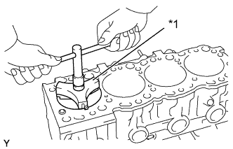
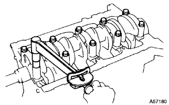
Text in Illustration *1 Ridge Reamer Using a ridge reamer, remove all the carbon from the top of the cylinder.
-
Cover the connecting rod bolts with a short piece of hose to protect the crankshaft from damage.
-
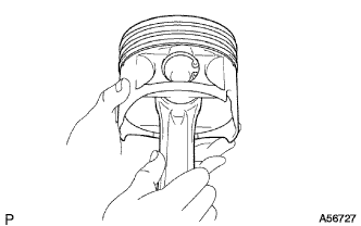
Push the piston, connecting rod assembly and upper bearing through the top of the cylinder block.
Tech Tips
-
Keep the bearings, connecting rod and cap together.
-
Arrange the piston and connecting rod assemblies in correct order.
-
-
-
REMOVE W/PIN PISTON SUB-ASSEMBLY
-
Check fit between the piston and piston pin.
-
Try to move the piston back and forth on the piston pin.
If any movement is felt, replace the piston and pin as a set.
-
-
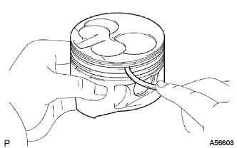
Remove the piston rings.
-
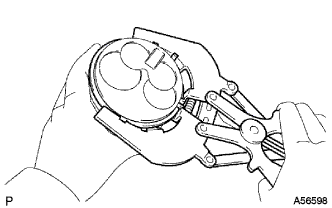
Using a piston ring expander, remove the 2 compression rings.
-
Remove the 2 side rails and oil ring by hand.
Tech Tips
Arrange the piston rings in correct order only.
-
-
Disconnect the connecting rod from the piston.
-
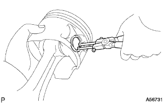
Using snap ring pliers, remove the snap rings.
-
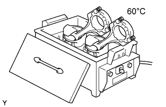
Gradually heat the piston to approx. 60°C (140°F).
-
Using a plastic-faced hammer and brass bar, lightly tap out the piston pin and pin and remove the connecting rod.
Tech Tips
-
The piston and pin are a matched set.
-
Arrange the pistons, pins, rings, connecting rods and bearings in correct order.
-
-
-
-
INSPECT CRANKSHAFT THRUST CLEARANCE
-
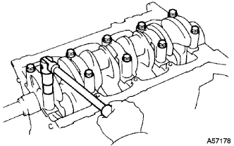
Using a dial indicator, measure the thrust clearance while prying the crankshaft back and forth with a screwdriver.
Standard thrust clearance 0.040 - 0.250 mm (0.0016 - 0.0098 in.) Maximum thrust clearance 0.30 mm (0.0118 in.) If the thrust clearance is greater than maximum, replace the thrust washers as a set.
Thrust washer thickness STD 2.430 - 2.480 mm (0.0957 - 0.0976 in.) O/S 0.125 2.493 - 2.543 mm (0.0981 - 0.1001 in.) O/S 0.250 2.555 - 2.605 mm (0.1006 - 0.1026 in.)
-
-
INSPECT CRANKSHAFT OIL CLEARANCE
-
Remove the 10 crankshaft bearing cap bolts.
-
Using the removed crankshaft bearing cap bolts, pry the cap back and forth, and remove the crankshaft bearing caps, lower bearings and lower thrust washers (No. 3 crankshaft bearing cap only).
Tech Tips
-
Keep the lower bearing and crankshaft bearings cap together.
-
Arrange the thrust washers in correct order.
-
-
Lift out the crankshaft.
Tech Tips
Keep the upper crankshaft bearings and upper thrust washers together with the cylinder block.
-
Clean each main journal and bearing.
-
Check each main journal and bearing for pitting and scratches.
If the journal or bearing is damaged, replace the bearings. If necessary, grind or replace the crankshaft.
-
Place the crankshaft on the cylinder block.
-
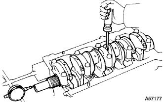
Text in Illustration *1 Plastigage Lay a strip of Plastigage across each journal.
-
Install the 5 crankshaft bearing caps with the 10 bolts (See step Click here).
Note
Do not turn the crankshaft.
-
Remove the 10 bolts and 5 crankshaft bearing caps (See procedure (a) and (b) above).
-
Text in Illustration *1 Plastigage 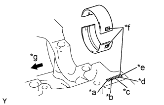
Text in Illustration *a No. 1 *b No. 2 *c No. 3 *d No. 4 *e No. 5 *f Mark 1, 2 or 3 *g Front Measure the Plastigage at its widest point.
Standard oil clearance STD 0.034 - 0.065 mm (0.0013 - 0.0026 in.) U/S 0.25, U/S 0.50 0.033 - 0.079 mm (0.0013 - 0.0031 in.) Maximum clearance 0.10 mm (0.0039 in.) If the oil clearance is greater than maximum, replace the bearings. If necessary, grind or replace the crankshaft.
Tech Tips
If using a standard bearing, replace it with one having the same number marked on the connecting rod cap. There are 3 sizes of standard bearings, marked 1, 2 and 3 accordingly.
Standard sized bearing center wall thickness Mark 1 1.979 - 1.983 mm (0.0779 - 0.0781 in.) Mark 2 1.983 - 1.987 mm (0.0781 - 0.0782 in.) Mark 3 1.987 - 1.991 mm (0.0782 - 0.0784 in.) -
Completely remove the Plastigage.
-
-
REMOVE CRANKSHAFT
-
Lift out the crankshaft.
-
Remove the upper bearings and upper thrust washers from the cylinder block.
Tech Tips
Arrange the crankshaft bearing caps, bearings and thrust washers in correct order.
-
-
REMOVE SUB-ASSEMBLY OIL NOZZLE NO. 1
-
Remove the 4 check valves and oil nozzles.
-
-
REMOVE CYLINDER BLOCK OIL ORIFICE
-
Using a 6 mm hexagon wrench, remove the oil orifice.
-
-
REMOVE CYLINDER BLOCK WATER DRAIN COCK SUB-ASSEMBLY
-
REMOVE W/HEAD TAPER SCREW PLUG NO.1
-
REMOVE OIL LEVEL GAGE GUIDE
-
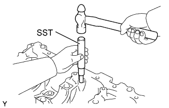
Using SST and a hammer, tap out the level gauge guide.
- SST
- 09201-10000 ( 09201-01070 )
- 09950-70010 ( 09951-07100 )
-
-
CLEAN CYLINDER BLOCK SUB-ASSEMBLY
-
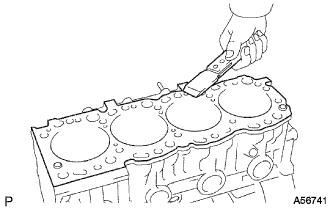
Using a gasket scraper, remove all the gasket material from the top surface of the cylinder block.
-
Using a soft brush and solvent, thoroughly clean the cylinder block.
-
-
CLEAN W/PIN PISTON SUB-ASSEMBLY
-

Using a gasket scraper, remove the carbon from the piston top.
-
Using a groove cleaning tool or broken ring, clean the piston ring grooves.
-
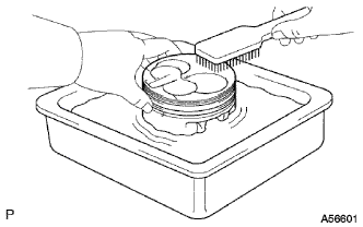
Using solvent and a brush, thoroughly clean the piston.
Note
Do not use a wire brush.
-
-
REMOVE CONNECTING ROD SMALL END BUSH
-
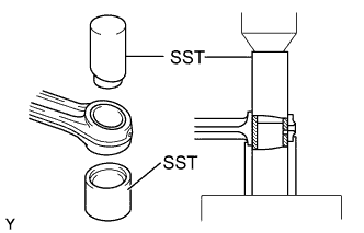
Using SST and a press, press out the bush.
- SST
- 09222-54011 ( 09222-03016, 09222-03026 )
-