CYLINDER HEAD INSPECTION

Tech Tips
-
Thoroughly clean all parts to be assembled.
-
Before installing the parts, apply fresh engine oil to all sliding and rotating surfaces.
-
Replace all gaskets and oil seals with new ones.
-
INSPECT CYLINDER HEAD SUB-ASSEMBLY
-
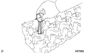
Inspect for flatness.
-
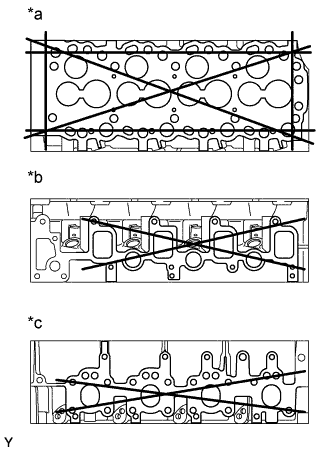
Text in Illustration *a Cylinder Block Side *b Intake Manifold Side *c Exhaust Manifold Side Using a precision straight edge and feeler gauge, measure the surfaces contacting the cylinder block and the manifolds for warpage.
Maximum warpage 0.20 mm (0.0079 in.) If warpage is greater than maximum, replace the cylinder head.
-
-
Inspect for cracks.
-
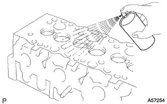
Using a dye penetrant, check the combustion chamber, intake ports, exhaust ports and cylinder block surface for cracks.
If cracked, replace the cylinder head.
-
-
-
INSPECT INTAKE VALVE
-
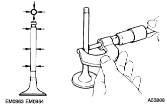
Using a micrometer, measure the diameter of the valve stem.
Valve stem diameter 7.975 - 7.990 mm (0.3140 - 0.3146 in.) -

Text in Illustration *a Valve Face Angle Check the valve face angle.
-
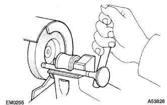
Grind the valve enough to remove pits and carbon.
-
Check that the valve is ground to the correct valve face angle.
Valve face angle 44.5°
-
-
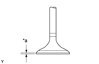
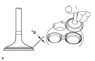
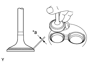
Text in Illustration *a Margin Thickness Check the valve head margin thickness.
Standard margin thickness 1.6 mm (0.063 in.) Minimum margin thickness 1.1 mm (0.043 in.) If the margin thickness is less than minimum, replace the valve.
-
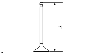
Text in Illustration *1 Overall Length Check the valve overall length.
Standard overall length 104.10 - 104.50 mm (4.0984 - 4.1142 in.) Minimum overall length 103.60 mm (4.0787 in.) If the overall length is less than minimum, replace the valve.
-
Check the surface of the valve stem tip for wear.
If the valve stem tip is worn, resurface the tip with a grinder or replace the valve.
Note
Do not grind off more than minimum.
-
-
INSPECT EXHAUST VALVE
-
Using a micrometer, measure the diameter of the valve stem.
Valve stem diameter 7.960 - 7.975 mm (0.3134 - 0.3140 in.) -
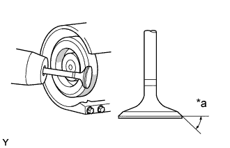
Text in Illustration *a Valve Face Angle Check the valve face angle.
-
Grind the valve enough to remove pits and carbon.
-
Check that the valve is ground to the correct valve face angle.
Valve face angle 44.5°
-
-
Text in Illustration *a Margin Thickness Check the valve head margin thickness.
Standard margin thickness 1.7 mm (0.067 in.) Minimum margin thickness 1.7 mm (0.067 in.) If the margin thickness is less than minimum, replace the valve.
-
Text in Illustration *1 Overall Length Check the valve overall length.
Standard overall length 103.95 - 104.35 mm (4.0925 - 4.1083 in.) Minimum overall length 103.45 mm (4.0728 in.) If the overall length is less than minimum, replace the valve.
-
Check the surface of the valve stem tip for wear.
If the valve stem tip is worn, resurface the tip with a grinder or replace the valve.
Note
Do not grind off more than minimum.
-
-
INSPECT INNER COMPRESSION SPRING
-
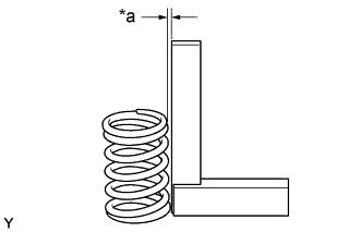
Text in Illustration *a Deviation Using a steel square, measure the deviation of the spring.
Maximum deviation 2.0 mm (0.079 in.) If the deviation is greater than maximum, replace the spring.
-
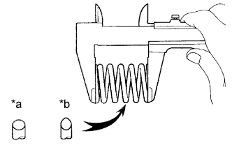
Text in Illustration *a Type A *b Type B Using vernier calipers, measure the free length of the spring.
Free length Type A 46.20 mm (1.8189 in.) Type B 48.54 mm (1.9110 in.) If the free length is not as specified, replace the spring.
-
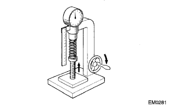
Using a spring tester, measure the tension of the valve spring at the specified installed length.
Installed tension 301 - 322 N (30.7 - 33.9 kgf, 67.7 - 74.7 lbf) at 37.0 mm (1.457 in.) If the installed tension is not as specified, replace the spring.
-
-
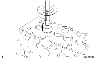
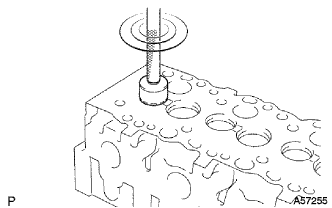
INSPECT INTAKE VALVE GUIDE BUSH
-
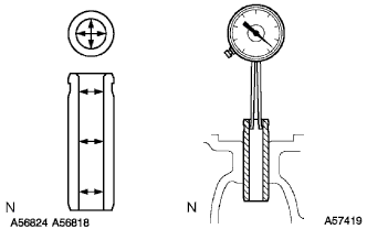
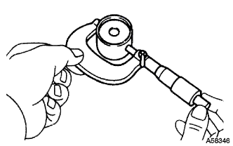
Using a caliper gauge, measure the inside diameter of the guide bush.
Bush inside diameter 8.010 - 8.030 mm (0.3154 - 0.3161 in.) -
Subtract the valve stem diameter measurement (See step 2) from the guide bush inside diameter measurement.
Standard oil clearance 0.020 - 0.055 mm (0.0008 - 0.0022 in.) Maximum oil clearance 0.08 mm (0.0031 in.) If the clearance is greater than maximum, replace the valve and guide bush (See steps 15 and 17).
-
Removal: Click here
-
Installation: Click here
-
-
-
INSPECT EXHAUST VALVE GUIDE BUSH
-
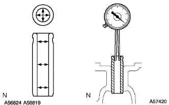
Using a caliper gauge, measure the inside diameter of the guide bush.
Bush inside diameter 8.010 - 8.030 mm (0.3154 - 0.3161 in.) -
Subtract the valve stem diameter measurement (See step 3) from the guide bush inside diameter measurement.
Standard oil clearance 0.035 - 0.070 mm (0.0014 - 0.0028 in.) Maximum oil clearance 0.10 mm (0.0039 in.) If the clearance is greater than maximum, replace the valve and guide bush (See steps 16 and 18).
-
Removal: Click here
-
Installation: Click here
-
-
-
INSPECT INTAKE VALVE SEATS
-
Using a 45° carbide cutter, resurface the valve seats. Remove only enough metal to clean the seats.
-
Text in Illustration *a Width Check the valve seating position.
-
Apply a light coat of prussian blue (or white lead) to the valve face.
-
Lightly press the valve against the seat. Do not rotate valve.
-
-
Check the valve face and seat for the following:
-
If blue appears 360° around the face, the valve is concentric. If not, replace the valve.
-
If blue appears 360° around the valve seat, the guide and face are concentric. If not, resurface the seat.
-
Check that the seat contact is in the middle of the valve face with the width:
Width 1.5 - 1.9 mm (0.059 - 0.075 in.)
-
-
-
INSPECT EXHAUST VALVE SEATS
-
Using a 45° carbide cutter, resurface the valve seats. Remove only enough metal to clean the seats.
-
Text in Illustration *a Width Check the valve seating position.
-
Apply a light coat of prussian blue (or white lead) to the valve face.
-
Lightly press the valve against the seat. Do not rotate valve.
-
-
Check the valve face and seat for the following:
-
If blue appears 360° around the face, the valve is concentric. If not, replace the valve.
-
If blue appears 360° around the valve seat, the guide and face are concentric. If not, resurface the seat.
-
Check that the seat contact is in the middle of the valve face with the width:
Width 1.8 - 2.2 mm (0.071 - 0.087 in.)
-
-
-
INSPECT VALVE LIFTER
-
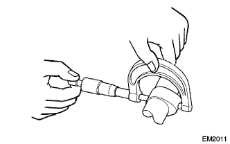
Using a micrometer, measure the lifter diameter.
Lifter diameter 40.892 - 40.902 mm (1.6099 - 1.6103 in.) -
Using a caliper gauge, measure the lifter bore diameter of the cylinder head.
Lifter bore diameter 40.960 - 40.980 mm (1.6126 - 1.6134 in.) -
Subtract the lifter diameter measurement from the lifter bore diameter measurement.
Standard oil clearance 0.058 - 0.088 mm (0.0023 - 0.0035 in.) Maximum oil clearance 0.10 mm (0.0039 in.) If the oil clearance is greater than maximum, replace the lifter.
If necessary, replace the cylinder head.
-
-
INSPECT CAMSHAFT
-
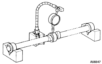
Inspect the circle runout.
-
Place the camshaft on V-blocks.
-
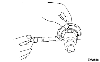
Using a dial indicator, measure the circle runout at the center journal.
Maximum circle runout 0.10 mm (0.0039 in) If the circle runout is greater than maximum, replace the camshaft.
-
-
Using a micrometer, measure the cam lobe height.
Standard cam lobe height Intake 54.290 - 54.310 mm (2.1374 - 2.1382 in.) Exhaust 54.990 - 55.010 mm (2.1650 - 2.1657 in.) Minimum cam lobe height Intake 53.79 mm (2.1177 in.) Exhaust 54.49 mm (2.1453 in.) If the cam lobe height is less than minimum, replace the camshaft.
-
Inspect the journal diameter of the camshaft.
-
Using a micrometer, measure the journal diameter of the camshaft for the camshaft bearing.
Journal diameter STD No. 1 34.969 - 34.985 mm (1.3767 - 1.3774 in.) Others 27.969 - 24.985 mm (1.1011 - 1.1018 in.) U/S 0.125 No. 1 34.844 - 34.860 mm (1.3718 - 1.3724 in.) Others 27.844 - 27.860 mm (1.0962 - 1.0968 in.) U/S 0.250 No. 1 34.719 - 34.735 mm (1.3669 - 1.3675 in.) Others 27.719 - 27.735 mm (1.0913 - 1.0919 in.) If the journal diameter is not as specified, check the oil clearance.
-
-
Check the oil clearance.
-
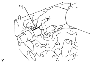
Clean the bearing caps and journals.
Text in Illustration *1 Plastigage -
Check that bearings for flaking and scoring.
If the bearings are damaged, If the bearings are damaged, replace the bearings.
-
Install the bearings to the bearing caps and cylinder head.
-
Place the camshaft on the cylinder head.
-
Lay a strip of Plastigage across each of the journals.
-
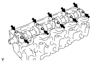
Install the bearing caps Click here .
Note
Do not turn the camshaft.
-
Remove the bearing caps.
-
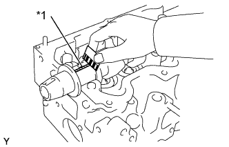
Text in Illustration *1 Plastigage Measure the Plastigage at its widest point.
Standard oil clearance 0.022 - 0.074 mm (0.0009 - 0.0029 in.) Maximum oil clearance Maximum oil clearance If the oil clearance is greater than maximum, replace the bearings. If necessary, grind or replace the camshaft.
-
Completely remove the Plastigage.
-
Remove the camshaft.
-
-
If necessary, grind and hone camshaft journals.
-
Grind and hone the journals to U/S diameter (See procedure (c) above). Install new journal U/S bearings.
-
-
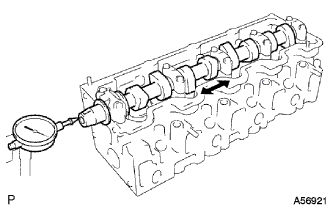
Check the thrust clearance.
-
Install the camshaft Click here.
-
Using a dial indicator, measure the thrust clearance while moving the camshaft back and forth.
Standard thrust clearance 0.080 - 0.280 mm (0.0031 - 0.0110 in.) Maximum thrust clearance 0.35 mm (0.0138 in.) If the thrust clearance is greater than maximum, replace the No.1 bearing. If necessary, replace the camshaft.
-
-