ENGINE UNIT REASSEMBLY

-
INSTALL ENGINE REAR OIL SEAL
Tech Tips
There are 2 methods (A and B) to install the oil seal.
-
If the rear oil seal retainer is removed from the cylinder block:
-
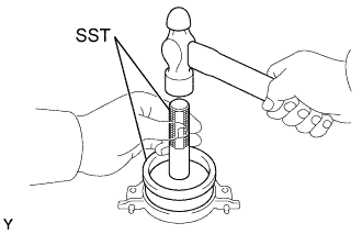
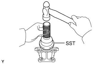
Using SST and a hammer, tap in a new oil seal until its surface is flush with the oil seal retainer edge.
- SST
- 09223-15030
- 09950-70010 ( 09951-07100 )
-
Apply MP grease to the oil seal lip.
-
-
If the rear oil seal retainer is installed to the cylinder block:
-
Apply MP grease to a new oil seal lip.
-
Using SST and a hammer, tap in the oil seal until its surface is flush with the rear oil seal retainer edge.
- SST
- 09223-15030
- 09950-70010 ( 09951-07100 )
-
-
-
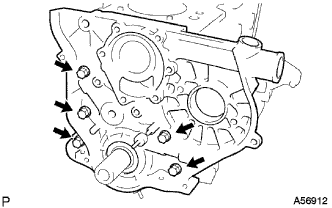
INSTALL ENGINE REAR OIL SEAL RETAINER
-
Install a new gasket and the retainer with the 4 bolts.
- Torque:
- 13 N*m { 130 kgf*cm, 10 ft.*lbf }
-
-
INSTALL TIMING GEAR CASE OR TIMING CHAIN CASE OIL SEAL
Tech Tips
There are 2 methods (A and B) to install the oil seal.
-
If the oil pump is removed from the cylinder block:
-
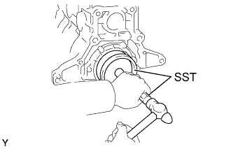
Using SST and a hammer, tap in a new oil seal to the depth of 0.5 mm (0.020 in.) from the oil pump case edge.
- SST
- 09214-60010
-
Apply MP grease to the oil seal lip.
-
-
If the oil pump is installed to the cylinder block:
-
Apply MP grease to a new oil seal lip.
-
Using SST and a hammer, tap in the oil seal to the depth of 0.5 mm (0.020 in.) from the oil pump case edge.
- SST
- 09214-60010
-
-
-
INSTALL TIMING GEAR CASE SUB-ASSEMBLY
-
Place a new gasket on the cylinder block.
-
Install the timing belt case with the 5 bolts.
- Torque:
- 22.5 N*m { 230 kgf*cm, 17 ft.*lbf }
-
-
INSTALL OIL STRAINER SUB-ASSEMBLY
-
Install a new gasket and oil strainer with the 2 bolts and 2 nuts.
- Torque:
- for Nut
- 21 N*m { 210 kgf*cm, 15 ft.*lbf }
- for Bolt
- 18 N*m { 180 kgf*cm, 13 ft.*lbf }
-
-
INSTALL OIL PAN SUB-ASSEMBLY
-
Remove any old packing (FIPG) material and be careful not to drop any oil on the contact surfaces of the oil pan and cylinder block.
-
Using a razor blade and gasket scraper, remove all the old packing (FIPG) material from the gasket surfaces and sealing groove.
-
Thoroughly clean all components to remove all the loose material.
-
Using a non-residue solvent, clean both sealing surfaces.
Note
Do not use a solvent which will affect the painted surfaces.
-
-
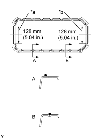
Text in Illustration *a Timing Belt Case Contact Portion *b Rear Oil Seal Contact Portion Apply seal packing to the oil pan as shown in the illustration.
Seal packing Toyota Genuine Seal Packing Black, Three Bond 1207B or equivalent Tech Tips
Apply at least 5 mm (0.20 in.) (preferably slightly more) of seal packing to the portions of the oil pan in contact with the timing belt case and rear oil seal retainer.
-
Install a nozzle that has been cut to a 4 - 5mm(0.16 - 0.20 in.) opening.
Tech Tips
Avoid applying an excessive amount to the surface. Be particularly careful near oil passages.
-
Parts must be assembled within 5 minutes of application. Otherwise the material must be removed and reapplied.
-
Immediately remove nozzle from the tube and reinstall cap.
-
-
Install be oil pan with the 14 bolts and 4 nuts. Uniformly tighten the bolts the bolts and nuts in several passes.
- Torque:
- 18 N*m { 180 kgf*cm, 13 ft.*lbf }
-
-
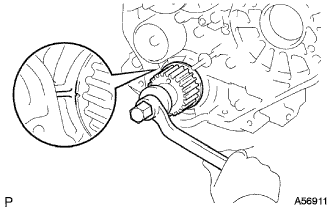
INSTALL CRANKSHAFT TIMING PULLEY
-
Align the pulley set key with the key groove of the timing pulley.
-
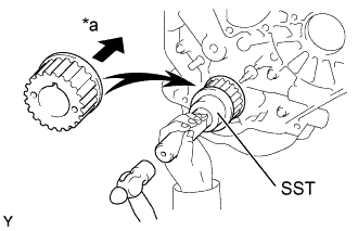
Text in Illustration *a Inside Using SST and a hammer, tap in the timing pulley, facing the flange side inward.
- SST
- 09223-46011
-
-
INSTALL WATER PUMP ASSEMBLY
-
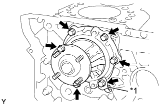
Text in Illustration *1 Bracket Install a new gasket, the water pump and tension spring bracket with the 6 bolts.
- Torque:
- 22.5 N*m { 230 kgf*cm, 17 ft.*lbf }
-
-
INSTALL TIMING BELT IDLER SUB-ASSEMBLY NO.2
-
Install the spacer and idler pulley with the bolt.
- Torque:
- 33 N*m { 340 kgf*cm, 24 ft.*lbf }
-
Check that the idler pulley moves smoothly.
-
-
INSTALL TIMING BELT IDLER SUB-ASSEMBLY NO.1
Tech Tips
-
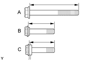
The bolt lengths for bolt types A, B and C shown in the illustration are:
A: 76.5 mm (3.012 in.)
B: 42.9 mm (1.689 in.), Color: Yellow
C: 41.3 mm (1.626 in.), Color: Silver
-
Bolt C is combined with the idler pulley.
-
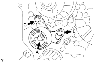
Install the idler pulley with the 3 bolts.
-
Tighten the bolt (C).
- Torque:
- 19 N*m { 195 kgf*cm, 14 ft.*lbf }
-
-
INSTALL CYLINDER HEAD SUB-ASSEMBLY
-
Check the piston protrusions for each cylinder.
-
Clean the cylinder block with solvent.
-
Set the piston of the cylinder to be measured to slightly before TDC.
-
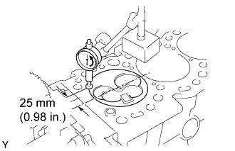
Place a dial indicator on the cylinder block, set the measuring tip as shown in the illustration.
-
Set the dial indicator at 0 mm (0 in.).
Tech Tips
-
Use a dial indicator measuring tip as shown in the illustration.
-
Make sure that the measuring tip is square to the cylinder block gasket surface and piston head when taking the measurements.
-
-
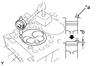
Text in Illustration *a Measuring Tip *b Protrusion Find where the piston head protrudes most by slowly turning the crankshaft clockwise and counterclockwise.
-
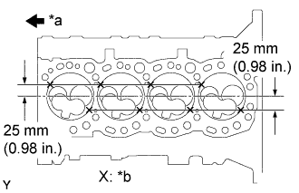
Text in Illustration *a Front *b Measuring Point Measure each cylinder at 2 places as shown in the illustration, making a total of 8 measurements.
-
For the piston protrusion value of each cylinder, use the average of the 2 measurements of each cylinder.
Piston protrusion 0.68 - 0.97 mm (0.0268 - 0.0382 in.) Tech Tips
When removing piston and connecting rod assembly: If the protrusion is not as specified, remove the piston and connecting rod assembly and reinstall it Click here.
-
-
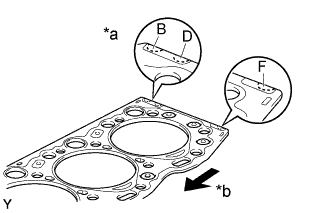
Text in Illustration *a Cutout Mark *b Front Select a new cylinder head gasket.
Tech Tips
There are 3 sizes of new cylinder head gaskets, marked B, D or F accordingly.
New installed cylinder head gasket thickness B 1.40 - 1.50 mm (0.0551 - 0.0591 in.) D 1.50 - 1.60 mm (0.0591 - 0.0630 in.) F 1.60 - 1.70 mm (0.0630 - 0.0669 in.)
-
Select the largest piston protrusion value from the measurements made, then select a new appropriate gasket according to the table below.
Piston protrusion Gasket size 0.68 - 0.77 mm (0.0268 - 0.0303 in.) Use B 0.78 - 0.87 mm (0.0307 - 0.0343 in.) Use D 0.88 - 0.97 mm (0.0346 - 0.0382 in.) Use F
-
-
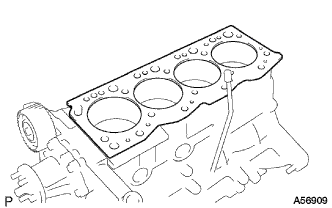
Place the cylinder head on the cylinder block.
-
Place the cylinder head gasket in position on the cylinder block.
Note
Be careful of the installation direction.
-
Place the cylinder head in position on the cylinder head gasket.
-
-
Install the cylinder head bolts.
Tech Tips
-
The cylinder head bolts are tightened in 3 progressive steps (steps (2), (4) and (5)).
-
If any bolts is broken or deformed, replace it.
-
Apply a light coat of engine oil on the threads and under the heads of the cylinder head bolts.
-
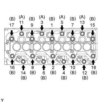
Install and uniformly tighten the 18 cylinder head bolts, in several passes, in the sequence shown.
- Torque:
- 78 N*m { 800 kgf*cm, 58 ft.*lbf }
Tech Tips
Each bolt length is indicated in the illustration.
Bolt length 107 mm (4.12 in.) for A 127 mm (5.00 in.) for B If any one of the cylinder head bolts does not meet the torque specification, replace the cylinder head bolt.
-
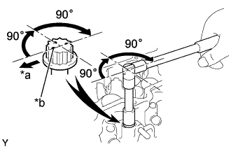
Text in Illustration *a Front *b Painted Mark Mark the front of the cylinder head bolt with paint.
-
Retighten the cylinder head bolts 90°in the numerical order shown.
-
Retighten cylinder head bolts by an additional 90°.
-
Check that the painted mark is now facing rearward.
-
-
-
INSTALL CAMSHAFT
-
Set the No. 1 cylinder to 90°BTDC/compression.
Tech Tips
Set the No. 1 cylinder to 90° BTDC/compression to avoid interference with the piston top and valve head.
-
Using the crankshaft pulley bolt, turn the crankshaft, and put the timing mark of the crankshaft timing pulley with the protrusion of the timing belt case.
-
-
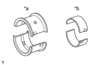
Install the camshaft.
Text in Illustration *a No. 1 *b Others Tech Tips
Different the bearing are used for the No. 1 and others.
-
Install the 10 bearings to the bearing caps and cylinder head.
-
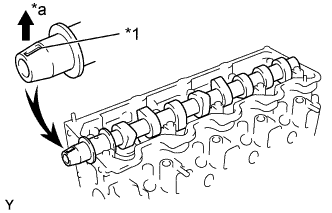
Text in Illustration *1 Key Groove *a Upward Place the camshaft on the cylinder head, facing the key groove upward.
-
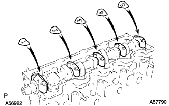
Install the 5 bearing caps in their proper locations.
-
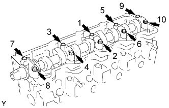
Apply a light coat of engine oil on the threads and under the heads of the bearing cap bolts.
-
Install and uniformly tighten the 10 bearing cap bolts, in several passes, in the sequence shown.
- Torque:
- 25 N*m { 255 kgf*cm, 18 ft.*lbf }
-
-
-
INSTALL OIL SEAL RETAINER, NO.2 OIL SEAL
Tech Tips
There are 2 methods (A and B) to install the oil seal.
-
If the camshaft oil seal retainer is removed from the cylinder head:
-
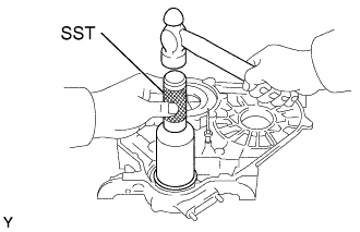
Using SST and a hammer, tap in a new oil seal until its surface is flush with the oil seal retainer edge.
- SST
- 09223-46011
-
Apply MP grease to the oil seal lip.
-
-
If the camshaft oil seal retainer is installed to the cylinder head:
-
Apply MP grease to a new oil seal lip.
-
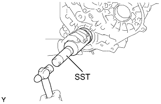
Using SST and a hammer, tap in the oil seal until its surface is flush with the oil seal retainer edge.
- SST
- 09223-46011
-
-
-
INSTALL CAMSHAFT OIL SEAL RETAINER
-
Install a new gasket and the retainer with the 4 bolts.
- Torque:
- 18 N*m { 185 kgf*cm, 13 ft.*lbf }
-
-
INSTALL TIMING BELT NO. 2 COVER
-
Install the timing belt cover with the 4 bolts.
- Torque:
- 18 N*m { 185 kgf*cm, 13 ft.*lbf }
-
-
INSTALL CAMSHAFT TIMING PULLEY
-
Install the set key to the key groove of the camshaft.
-
Align the pulley set key with the timing mark outward.
-
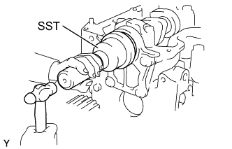
Using SST, install the pulley with the bolt.
- SST
- 09960-10010 ( 09962-01000, 09963-01000 )
- Torque:
- 98 N*m { 1,000 kgf*cm, 72 ft.*lbf }
-
-
INSPECT VALVE CLEARANCE
-
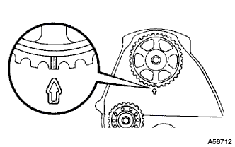
Align the timing mark of the camshaft timing pulley with the arrow mark of the timing belt No. 2 cover.
-
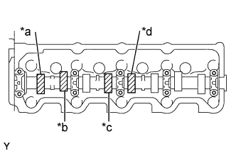
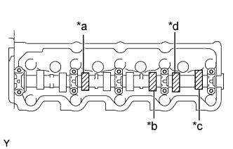
Text in Illustration *a No. 1 EX *b No. 1 IN *c No. 2 IN *d No. 3 EX Check only the valves indicated.
-
Using a feeler gauge, measure the clearance between the valve lifter and camshaft.
-
Record the out-of-specification valve clearance measurements. They will be used later to determine the required replacement adjusting shim.
Valve clearance (Cold) Intake 0.20 - 0.30 mm (0.008 - 0.012 in.) Exhaust 0.40 - 0.50 mm (0.016 - 0.020 in.)
-
-
Text in Illustration *a No. 2 EX *b No. 3 IN *c No. 4 IN *d No. 4 EX Turn the camshaft 1/2 revolutions (180°).
-
Check only the valves indicated as shown. Measure the valve clearance (See procedure (b) above).
-
-
ADJUST VALVE CLEARANCE
-
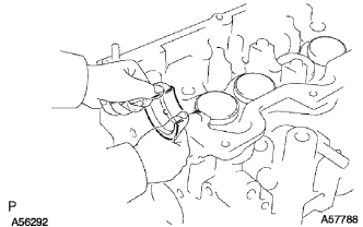
Remove the adjusting shim.
-
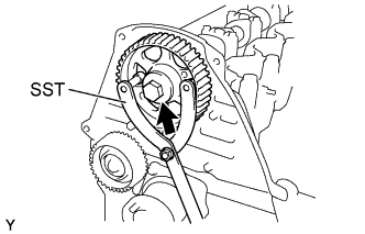
Turn the crankshaft so that the cam lobe of the camshaft on the adjusting valve points upward.
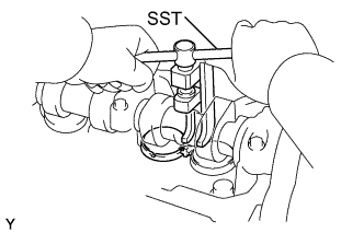
-
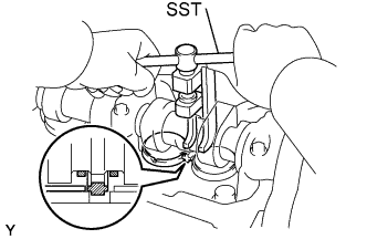
Using SST, press down the valve lifter.
- SST
- 09248-64011
-
Position the notch of the valve lifter facing the exhaust manifold side.
-
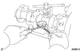
Remove the adjusting shim with a small screwdriver and magnetic finger.
-
-
Determine the replacement adjusting shim size by following the Formula or Charts:
-
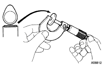
Using a micrometer, measure the thickness of the removed shim.
-
Calculate the thickness of a new shim so that the valve clearance comes within specified value.
T = Thickness of removed shim
A = Measured valve clearance
N = Thickness of new shim
Intake of new shim Intake N = T + (A - 0.25 mm (0.010 in.)) Exhaust N = T + (A - 0.45 mm (0.018 in.)) -
Select a new shim with a thickness as close as possible to the calculated value.
Tech Tips
Shims are available in 17 sizes in increments of 0.05 mm (0.0020 in.), from 2.50 mm (0.0984 in.) to 3.30 mm (0.1299 in.).
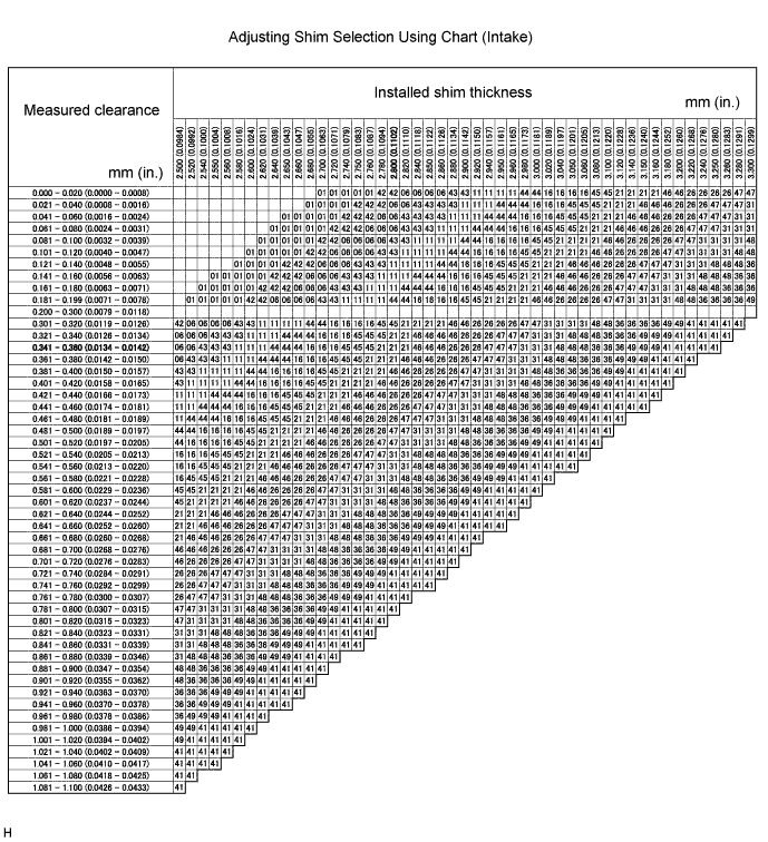
Intake valve clearance (Cold) 0.20 - 0.30 mm (0.008 - 0.012 in.) EXAMPLE The 2.800 mm (0.1102 in.) shim is installed and the measured clearance is 0.350 mm (0.0138 in.). Replace the 2.800 mm (0.1102 in.) shim with a No. 21 shim. New shim thickness mm (in.) Shim No. Thickness Shim No. Thickness 01 2.50 (0.0984) 46 2.95 (0.1161) 42 2.55 (0.1004) 26 3.00 (0.1181) 06 2.60 (0.1024) 47 3.05 (0.1201) 43 2.65 (0.1043) 31 3.10 (0.1220) 11 2.70 (0.1063) 48 3.15 (0.1240) 44 2.75 (0.1083) 36 3.20 (0.1260) 16 2.80 (0.1102) 49 3.25 (0.1280) 45 2.85 (0.1122) 41 3.30 (0.1299) 21 2.90 (0.1142) - - 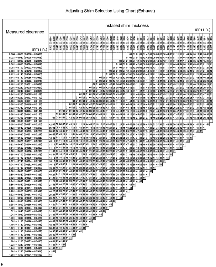
Exhaust valve clearance (Cold) 0.40 - 0.50mm(0.016 - 0.020 in.) EXAMPLE The 2.800mm (0.1102 in.) shim is installed and the measured is 0.350 mm (0.0138 in.). Replace the 2.800 mm (0.1102 in.) shim with a No. 11 shim. New shim thickness mm (in.) Shim No. Thickness Shim No. Thickness 01 2.50 (0.0984) 46 2.95 (0.1161) 42 2.55 (0.1004) 26 3.00 (0.1181) 06 2.60 (0.1024) 47 3.05 (0.1201) 43 2.65 (0.1043) 31 3.10 (0.1220) 11 2.70 (0.1063) 48 3.15 (0.1240) 44 2.75 (0.1083) 36 3.20 (0.1260) 16 2.80 (0.1102) 49 3.25 (0.1280) 45 2.85 (0.1122) 41 3.30 (0.1299) 21 2.90 (0.1142) - -
-
-
Install a new adjusting shim.
-
Place a new adjusting shim on the valve lifter.
-
Remove the SST.
- SST
- 09248-64011
-
-
Recheck the valve clearance. 41.
-
-
INSTALL CYLINDER HEAD COVER SUB-ASSEMBLY
-
Remove any old packing (FIPG) material.
-
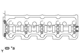
Text in Illustration *a Seal Packing Apply seal packing to the cylinder head as shown in the illustration.
Seal packing Toyota Genuine Seal Packing Black, Three Bond 1207B or equivalent -
Install the gasket to the cylinder head cover.
-
Install the cylinder head cover with 8 bolts and 2 nuts. Uniformly tighten the bolts and nuts in several passes.
- Torque:
- 12 N*m { 120 kgf*cm, 9 ft.*lbf }
-
-
INSTALL OIL FILLER CAP SUB-ASSEMBLY