CYLINDER HEAD (w/o DPF) REMOVAL

-
DRAIN ENGINE OIL
-
Remove the oil filler cap.
-
Remove the drain plug from the oil pan and drain the engine oil into a container.
-
Clean the drain plug.
-
Install the drain plug with a new gasket.
- Torque:
- 34 N*m { 347 kgf*cm, 25 ft.*lbf }
-
-
REMOVE TIMING BELT
Refer to the procedures up to "REMOVE TIMING BELT" Click here.
-
REMOVE INJECTOR ASSEMBLY
Refer to the procedures up to "REMOVE INJECTOR ASSEMBLY" Click here.
-
REMOVE COMMON RAIL ASSEMBLY
-
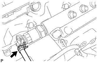
Disconnect the 2 connectors from the common rail.
-
Disconnect the fuel hose.
-
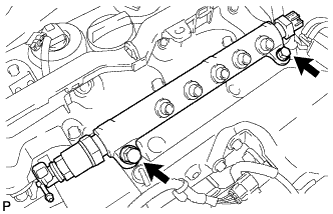
Remove the 2 bolts and remove the common rail.
-
-
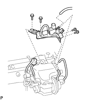
REMOVE MANIFOLD STAY
-
Separate the 3 vacuum hoses and gas filter.
-
Remove the 4 bolts and remove the manifold stay.
-
-
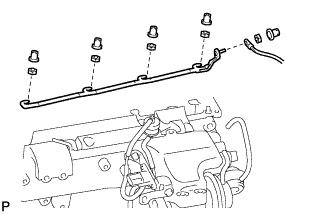
REMOVE NO. 1 GLOW PLUG CONNECTOR
-
Remove the screw grommet and nut and separate the wire harness from the No. 1 glow plug connector.
-
Remove the 4 screw grommets and 4 nuts and remove the No.1 glow plug connector.
-
-
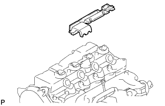
REMOVE NO. 2 INTAKE MANIFOLD INSULATOR
-
Remove the No. 2 intake manifold Insulator.
-
-
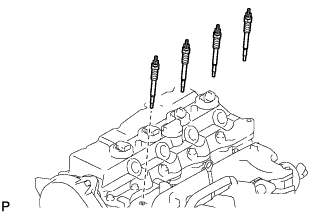
REMOVE GLOW PLUG ASSEMBLY
-
Remove the 4 glow plugs.
-
-
REMOVE NO. 1 INTAKE MANIFOLD INSULATOR
-
REMOVE FUEL COOLER
-
Remove the 2 bolts and fuel cooler.
-
-
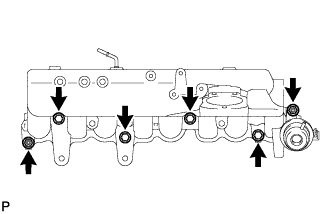
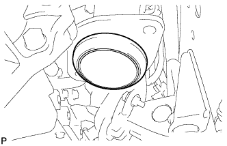
REMOVE INTAKE MANIFOLD
-
Remove the 2 nuts and 4 bolts, then remove the intake manifold and gasket.
-
-
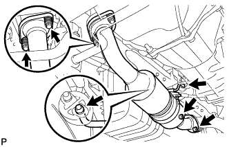
REMOVE FRONT EXHAUST PIPE ASSEMBLY
-
Remove the 2 nuts and the 2 bolts from the center exhaust pipe.
-

Remove the gasket from the front exhaust pipe.
-
Remove the 2 bolts and the 2 compression springs from the turbine outlet elbow.
-
Remove the 2 hooks and the front exhaust pipe.
-
Remove the gasket from the turbine outlet elbow.
-
-
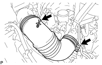
DISCONNECT NO. 1 AIR HOSE
-
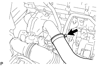
Loosen the hose clamp and disconnect the No. 1 air hose .
-
-
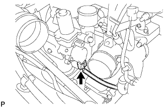
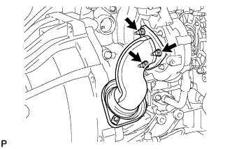
REMOVE COMPRESSOR OUTLET ELBOW
-
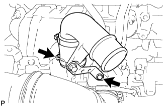
Remove the hose clamp and bolt shown in the illustration and remove the compressor outlet elbow with No. 2 air hose.
-
-
DISCONNECT TURBOCHARGER MOTOR CONNECTOR
-
Disconnect the turbocharger motor connector from the turbocharger.
-
-
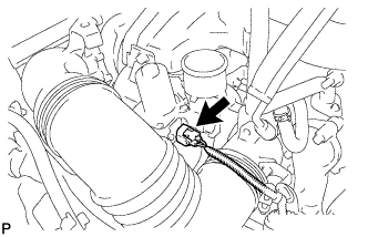
REMOVE NO. 2 AIR CLEANER HOSE
-
Loosen the hose clamp and remove the NO. 2 air cleaner hose.
-
-
DISCONNECT TURBOCHARGER STROKE SENSOR CONNECTOR
-
Disconnect the turbocharger stroke sensor connector from the turbocharger.
-
-
SEPARATE ENGINE WIRE HARNESS (for LHD)
-
Remove the 2 bolts and separate the engine wire harness with bracket.
-
-
SEPARATE ENGINE WIRE HARNESS (for RHD)
-
Remove the 2 bolts and separate the engine wire harness with bracket.
-
-
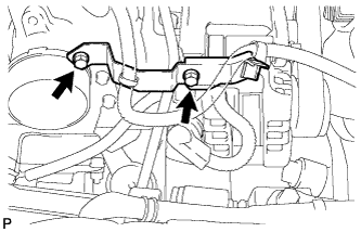
REMOVE VENTILATION PIPE SUB-ASSEMBLY
-
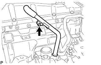
Remove the bolt and ventilation pipe sub-assembly.
-
-
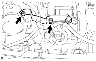
REMOVE NO. 1 TURBO INSULATOR
-
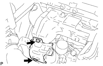
Remove the 2 bolts and turbo insulator No. 1.
-
-
REMOVE NO. 1 EXHAUST MANIFOLD HEAT INSULATOR
-
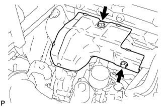
Remove the 2 bolts and No. 1 exhaust manifold heat insulator.
-
-
DISCONNECT NO. 1 TURBO WATER HOSE
-
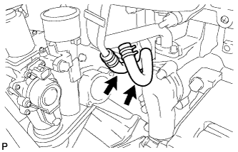
Loosen the 2 clamps and disconnect No. 1 turbo water hose.
-
-
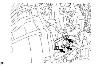
REMOVE TURBINE OUTLET ELBOW
-
Remove the 3 nuts, turbine outlet elbow and gasket.
-
-
REMOVE TURBOCHARGER STAY
-
Remove the 2 bolts and nut and remove the turbocharger stay.
-
-
REMOVE TURBO OIL INLET PIPE SUB-ASSEMBLY
-
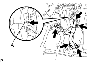
Remove the 2 bolts, 2 nuts and union bolt, then remove the turbo oil inlet pipe sub-assembly and gasket.
Note
Do not loosen the nut labeled A.
-
-
REMOVE OIL LEVEL GAUGE GUIDE (for LHD)
-
Remove the oil level gauge.
-
Remove the bolt and oil level gauge guide.
-
Remove the O-ring from the oil level gauge guide.
-
-
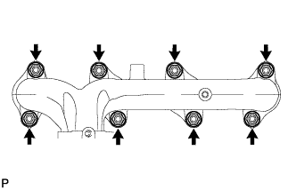
REMOVE EXHAUST MANIFOLD
-
Remove the 8 nuts, and then remove the exhaust manifold.
-
-
REMOVE CAMSHAFT TIMING PULLEY
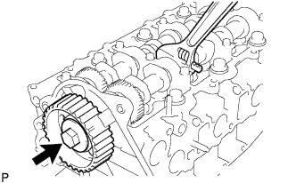
-
Remove the bolt from the camshaft timing pulley while holding the camshaft with a wrench.
-
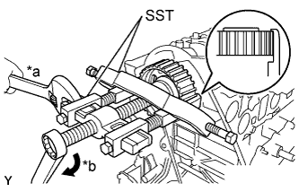
Text in Illustration *a Hold *b Turn Using SST, remove the camshaft timing pulley and set key.
- SST
- 09950-40011 ( 09951-04010, 09952-04010, 09953-04020, 09954-04010, 09955-04071, 09957-04010, 09958-04011 )
-
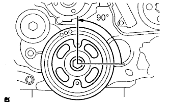
Rotate the crankshaft approximately 90° counterclockwise from the TDC position to lower the piston.
-
-
REMOVE NO. 2 TIMING BELT COVER
-
Remove the 4 bolts, nut and timing belt cover.
-
-
REMOVE CYLINDER BLOCK INSULATOR
-
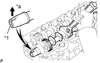
REMOVE NO.2 CAMSHAFT
-
Face the key groove of the camshaft upward by turning the camshaft with a wrench.
Text in Illustration *1 Key Groove *a Upward -
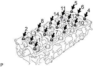
Uniformly loosen the 15 bearing cap bolts in several steps in the sequence shown in the illustration.
-
Remove the 5 bearing caps.
-
Remove the No. 2 camshaft.
-
-
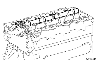
REMOVE CAMSHAFT
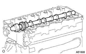
-
Remove the camshaft.
-
-
REMOVE CAMSHAFT SETTING OIL SEAL
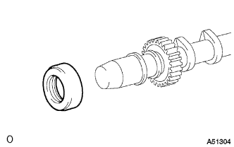
-
Remove the oil seal from the camshaft.
-
-
REMOVE CYLINDER HEAD SUB-ASSEMBLY
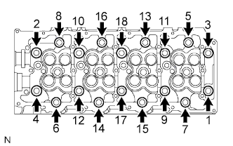
-
Uniformly loosen the 18 cylinder head bolts in several passes in the sequence shown in the illustration. Then remove the 18 cylinder head bolts and 18 washers.
Note
Head warpage or cracking could result from removing bolts in the incorrect order.
-
Lift the cylinder head from the dowels on the cylinder block, and place the cylinder head on wooden blocks on a bench.
Tech Tips
If the cylinder head is difficult to lift, use a screwdriver to pry between the cylinder head and block.
Note
Be careful not to damage the contact surfaces of the cylinder head and cylinder block.
-
-
REMOVE CYLINDER HEAD GASKET