CYLINDER HEAD (w/ DPF) INSTALLATION
Note
-
When replacing the injectors (including shuffling the injectors between the cylinders), common rail or cylinder head, it is necessary to replace the injection pipes with new ones.
-
When replacing the fuel supply pump, common rail, cylinder block, cylinder head, cylinder head gasket or timing gear case, it is necessary to replace the fuel inlet pipe with a new one.
-
After removing the injection pipes and fuel inlet pipe, clean them with a brush and compressed air.
-
INSTALL CYLINDER HEAD GASKET
-
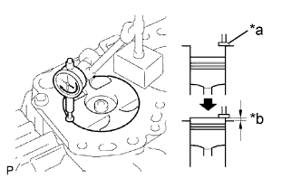
Find where the piston head protrudes most by slowly turning the crankshaft clockwise and counterclockwise.
Text in Illustration *a Measuring Tip *b Protrusion -
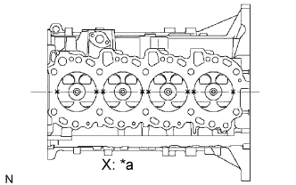
Text in Illustration *a Measuring Point Measure the piston protrusion of each cylinder at 2 points as shown in the illustration.
-
For the piston protrusion value of each cylinder, use the average of the 2 measurements of that cylinder.
Standard piston protrusion 0.005 to 0.254 mm (0.0002 to 0.0100 in.) Tech Tips
If the protrusion is not as specified, remove the piston and connecting rod assembly and reinstall them.
-
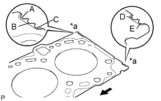
Text in Illustration *a Cutout Mark 
Front Select a new cylinder head gasket.
Tech Tips
New cylinder head gaskets are available in 5 sizes, and are marked A, B, C, D or E.
New Installed Cylinder Head Gasket Thickness Item Specified Condition A 0.80 to 0.90 mm (0.0315 to 0.0354 in.) B 0.85 to 0.95 mm (0.0335 to 0.0374 in.) C 0.90 to 1.00 mm (0.0354 to 0.0394 in.) D 0.95 to 1.05 mm (0.0374 to 0.0413 in.) E 1.00 to 1.10 mm (0.0394 to 0.0433 in.)
-
Select the largest piston protrusion value from the measurements made. Then select a new appropriate gasket according to the table below.
Gasket Size to be Used Gasket Size Gasket Size A 0.005 to 0.054 mm (0.0002 to 0.0021 in.) B 0.055 to 0.104 mm (0.0022 to 0.0041 in.) C 0.105 to 0.154 mm (0.0041 to 0.0061 in.) D 0.155 to 0.204 mm (0.0061 to 0.0080 in.) E 0.155 to 0.204 mm (0.0061 to 0.0080 in.)
-
-
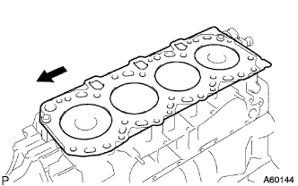
Place the cylinder head on the cylinder block.
Text in Illustration Front
-
Place the cylinder head gasket on the cylinder block.
Note
Make sure the gasket is installed in the collect direction.
-
Place the cylinder head on the cylinder head gasket.
-
-
-
INSTALL CYLINDER HEAD SUB-ASSEMBLY
Tech Tips
-
The cylinder head bolts are tightened in 3 progressive steps.
-
If any bolt is broken or deformed, replace it.
-
Apply a light coat of engine oil to the threads and under the heads of the cylinder head bolts.
-
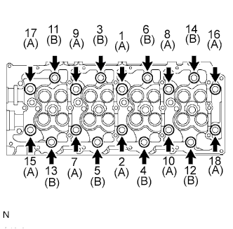
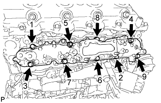
Install and uniformly tighten the 18 cylinder head bolts and 18 washers in several passes in the sequence shown in the illustration.
- Torque:
- 85 N*m { 867 kgf*cm, 63 ft.*lbf }
Bolt Length A 110 mm (4.33 in.) B 167 mm (6.57 in.) If any of the cylinder head bolts does not meet the torque specification, replace it.
-
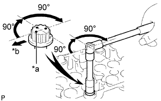
Text in Illustration *a Painted Mark *b Front Mark the front of the cylinder head bolts with paint.
-
Further tighten the cylinder head bolts by 90° in the sequence shown in the illustration above.
-
Finally, tighten the cylinder head bolts by an additional 90°.
-
Check that the painted marks are now facing rearward.
-
-
INSTALL CYLINDER BLOCK INSULATOR
-
Install the cylinder block insulator to the cylinder head.
-
-
INSTALL SWIRL CONTROL VALVE ASSEMBLY
-
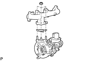
Temporarily install a new gasket and the swirl control valve with the 4 bolts and 2 nuts.
Note
Make sure that the swirl control valve actuator is not damaged by the surrounding parts.
-
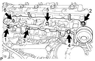
Tighten the 4 bolts and 2 nuts in the order shown in the illustration.
- Torque:
- 29 N*m { 296 kgf*cm, 21 ft.*lbf }
-
-
INSTALL VACUUM CONTROL VALVE SET
-
Install the vacuum control valve set with the 2 bolts.
- Torque:
- 20 N*m { 204 kgf*cm, 15 ft.*lbf }
-
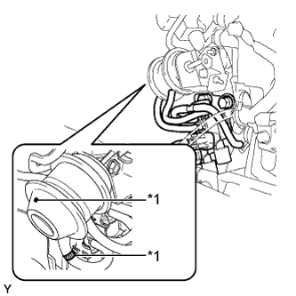
Text in Illustration *1 Paint Mark Connect the 3 vacuum hoses and 2 connectors.
Tech Tips
When connecting the hoses, match the color of the paint mark on the hoses to the color of the paint mark on the swirl control valve as shown in the illustration.
-
-
INSTALL INTAKE MANIFOLD
-
Temporarily install a new gasket and the intake manifold with the 7 bolts and 2 nuts.
-
Tighten the 7 bolts and 2 nuts in the order shown in the illustration.
- Torque:
- 20 N*m { 204 kgf*cm, 15 ft.*lbf }
-
-
INSTALL NO. 1 INTAKE MANIFOLD INSULATOR
-
Install the No. 1 intake manifold insulator to the intake manifold.
-
-
INSTALL INTAKE MANIFOLD STAY
-
Install the intake manifold stay with the 2 bolts.
- Torque:
- 21 N*m { 214 kgf*cm, 15 ft.*lbf }
-
-
TEMPORARILY TIGHTEN EXHAUST MANIFOLD
-
Install a new gasket and the turbocharger with 3 new nuts to the exhaust manifold.
- Torque:
- 52 N*m { 530 kgf*cm, 38 ft.*lbf }
Note
The claws of the gasket must face the turbocharger.
-
Install a new gasket to the cylinder head.
-
Temporarily tighten the exhaust manifold with turbocharger, 8 plate washers, 8 collars with 8 new nuts.
Note
Make sure that the side of the collar with the smaller diameter faces the exhaust manifold.
-
Connect the 3 water hoses.
-
-
TEMPORARILY TIGHTEN TURBO OIL INLET PIPE SUB-ASSEMBLY
-
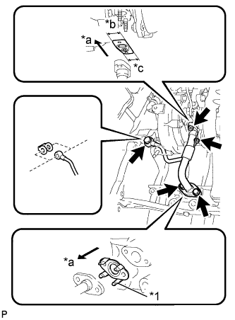
Text in Illustration *1 Claw *a Outside *b Wide *c Narrow Install 2 new gaskets to the turbo oil inlet pipe.
Note
Insert the gasket with its claws facing the turbo oil inlet pipe.
-
Temporarily tighten the gasket and turbo inlet pipe with the 2 bolts, 2 nuts and union bolt.
-
-
TEMPORARILY TIGHTEN TURBOCHARGER STAY
-
Temporarily tighten the turbocharger stay with the 2 bolts and a new nut.
-
-
FULLY TIGHTEN EXHAUST MANIFOLD
-
Fully tighten the 8 exhaust manifold installation nuts.
- Torque:
- 40 N*m { 408 kgf*cm, 30 ft.*lbf }
-
-
FULLY TIGHTEN TURBOCHARGER STAY
-
Fully tighten the 2 bolts and nut to the specified torque and install the turbocharger stay.
- Torque:
- 38 N*m { 387 kgf*cm, 28 ft.*lbf }
-
-
FULLY TIGHTEN TURBO OIL INLET PIPE SUB-ASSEMBLY
-
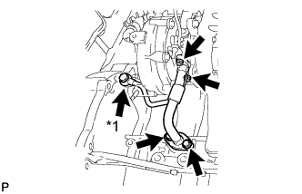
Text in Illustration *1 Union Bolt Fully tighten the 2 bolts, 2 nuts and union bolt to the specified torque and install the turbo oil inlet pipe.
- Torque:
- Bolt
- 12 N*m { 122 kgf*cm, 9 ft.*lbf }
- Nut
- 13 N*m { 133 kgf*cm, 10 ft.*lbf }
- Union Bolt
- 26 N*m { 265 kgf*cm, 19 ft.*lbf }
-
-
TEMPORARILY TIGHTEN NO. 1 EXHAUST MANIFOLD HEAT INSULATOR
-
Temporarily tighten the No. 1 exhaust manifold heat insulator with the 3 bolts.
-
-
INSTALL NO. 1 TURBO INSULATOR
-
Temporarily tighten the No. 1 turbo insulator with the 2 bolts.
-
Fully tighten the 5 bolts to the specified torque and install the No. 1 exhaust manifold heat insulator and No. 1 turbo insulator.
- Torque:
- 12 N*m { 122 kgf*cm, 9 ft.*lbf }
-
-
INSTALL TURBINE OUTLET ELBOW
-
Connect the No. 4 water by-pass pipe to the No. 13 water by-pass pipe.
-
Temporarily tighten the turbine outlet elbow with a new gasket and 3 new nuts.
-
Temporarily tighten the No. 3 fuel pipe with a new gasket and union bolt.
-
Fully tighten the 3 nuts to the specified torque and install the turbine outlet elbow.
- Torque:
- 30 N*m { 306 kgf*cm, 22 ft.*lbf }
-
Fully tighten the union bolt to the specified torque and install the No. 3 fuel pipe.
- Torque:
- 30 N*m { 306 kgf*cm, 22 ft.*lbf }
-
Install a new gasket and No. 4 water by-pass pipe with the union bolt.
- Torque:
- 30 N*m { 306 kgf*cm, 22 ft.*lbf }
-
Connect the No. 1 turbo water hose.
-
Connect the addition injector connector.
-
-
INSTALL NO. 2 FUEL PIPE CLAMP
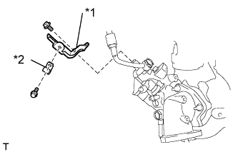
Text in Illustration *1 No. 2 Fuel Pipe Clamp *2 No. 3 Fuel Pipe Clamp
-
Install the No. 2 fuel pipe clamp with the bolt.
- Torque:
- 8.0 N*m { 82 kgf*cm, 71 in.*lbf }
-
Install the No. 3 fuel pipe clamp with the bolt.
- Torque:
- 6.5 N*m { 66 kgf*cm, 58 in.*lbf }
-
-
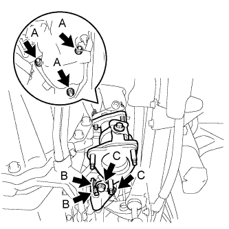
INSTALL CATALYTIC WITH PIPE CONVERTER ASSEMBLY
-
Fully tighten the 3 (A) nuts to the specified torque and install the catalytic with pipe converter.
- Torque:
- 30 N*m { 306 kgf*cm, 22 ft.*lbf }
-
Fully tighten the 2 (B) 2 bolts to the specified torque and install the turbine outlet stay.
- Torque:
- 62 N*m { 632 kgf*cm, 46 ft.*lbf }
-
Fully tighten the 2 (C) 2 bolts to the specified torque and install the turbine outlet stay.
- Torque:
- 62 N*m { 632 kgf*cm, 46 ft.*lbf }
-
-
INSTALL NO. 3 EXHAUST MANIFOLD HEAT INSULATOR
-
Install the No. 3 exhaust manifold heat insulator with the 2 bolts.
- Torque:
- 13 N*m { 133 kgf*cm, 10 ft.*lbf }
-
-
INSTALL NO. 2 EXHAUST MANIFOLD HEAT INSULATOR
-
Install the No. 2 exhaust manifold heat insulator with the 2 bolts.
- Torque:
- 13 N*m { 133 kgf*cm, 10 ft.*lbf }
-
-
INSTALL VENTILATION PIPE SUB-ASSEMBLY
-
Install the ventilation pipe with the bolt.
- Torque:
- 20 N*m { 204 kgf*cm, 15 ft.*lbf }
-
-
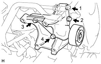
INSTALL NO. 1 COMPRESSOR MOUNTING BRACKET (w/ Air Conditioning System)
-
Temporarily install the No. 1 compressor mounting bracket with the 4 bolts.
-
Fully tighten the 4 bolts in the order shown in the illustration.
- Torque:
- 50 N*m { 510 kgf*cm, 37 ft.*lbf }
Tech Tips
Make sure that the No. 1 compressor mounting bracket is in contact with the cylinder block.
-
-
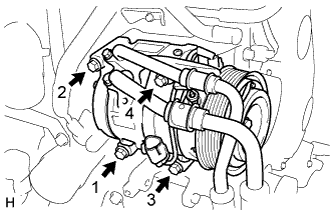
INSTALL COOLER COMPRESSOR ASSEMBLY (w/ Air Conditioning System)
-
Temporarily install the cooler compressor with the 4 bolts.
-
Fully tighten the 4 bolts in the order shown in the illustration.
- Torque:
- 25 N*m { 250 kgf*cm, 18 ft.*lbf }
-
-
INSTALL ENGINE OIL LEVEL DIPSTICK GUIDE (for LHD)
-
Apply clean engine oil to a new O-ring.
-
Install the O-ring to the level gauge.
-
Install the engine oil level dipstick guide with the bolt.
- Torque:
- 8.0 N*m { 82 kgf*cm, 71 in.*lbf }
-
Install the wire harness clamp bracket with the 2 bolts.
- Torque:
- 8.0 N*m { 82 kgf*cm, 71 in.*lbf }
-
Connect the wire harness to the wire harness clamp bracket.
-
-
INSTALL CAMSHAFTS
-
INSTALL TIMING BELT
-
INSPECT VALVE CLEARANCE
-
Check only the valves indicated.
-
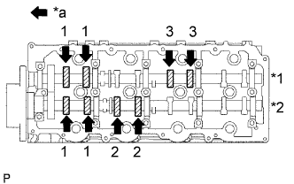
Text in Illustration *1 Exhaust *2 Intake *a Front Using a feeler gauge, measure the clearance between the valve lifter and camshaft.
Standard Valve Clearance (Cold) Intake Exhaust 0.20 to 0.30 mm (0.008 to 0.012 in.) 0.35 to 0.45 mm (0.014 to 0.018 in.) Write down the valve clearance measurements that are not within the specified range. These measurements will be used later to determine the size of the adjustment shim to be installed.
-
-
Turn the crankshaft 360° to set the No. 4 cylinder to TDC / compression.
-
Check only the valves indicated.
-
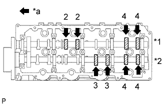
Text in Illustration *1 Exhaust *2 Intake *a Front Using a feeler gauge, measure the clearance between the valve lifter and camshaft.
Standard Valve Clearance (Cold) Intake Exhaust 0.20 to 0.30 mm (0.008 to 0.012 in.) 0.35 to 0.45 mm (0.014 to 0.018 in.) Write down the valve clearance measurements that are not within the specified range. These measurements will be used later to determine the size of the adjustment shim to be installed.
-
-
-
ADJUST VALVE CLEARANCE
-
Remove the camshafts Click here.
-
Remove the 8 valve lifters.
-
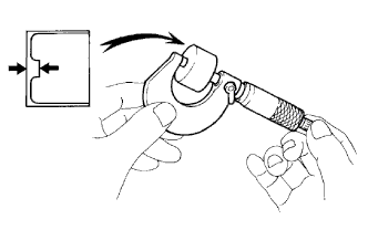
Using a micrometer, measure the thickness of the removed lifter.
-
Calculate the thickness of a new lifter so that the valve clearance comes within the specified value.
A B C New lifter thickness Used lifter thickness Measured valve clearance New Lifter Thickness Intake A = B + (C - 0.25 mm (0.0098 in.)) Exhaust A = B + (C - 0.40 mm (0.00157 in.)) -
Select a new lifter with a thickness as close as possible to the calculated values.
Tech Tips
Valve lifters are available in 35 sizes in increments of 0.020 mm (0.0008 in.), from 5.060 mm (0.1992 in.) to 5.740 mm (0.2260 in.).
-
Install the selected valve lifter.
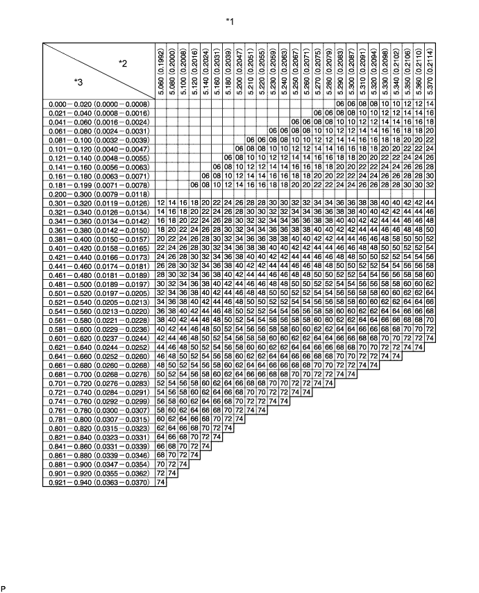
Text in Illustration *1 Valve Lifter Selection Chart (Intake) *2 Installed lifter thickness mm (in.) *3 Measured clearance mm (in.) - - 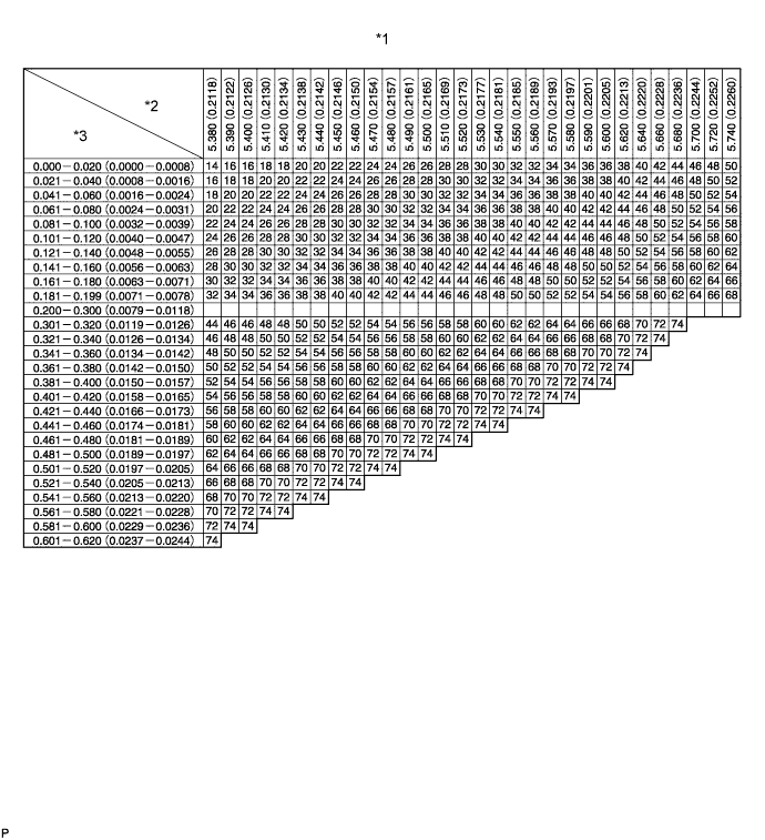
Text in Illustration *1 Valve Lifter Selection Chart (Intake) *2 Installed lifter thickness mm (in.) *3 Measured clearance mm (in.) - - Standard intake valve clearance (Cold) 0.20 to 0.30 mm (0.008 to 0.012 in.) EXAMPLE The 5.250 mm (0.2067 in.) lifter is installed, and the measured clearance is 0.400 mm (0.0157 in.). Replace the 5.250 mm (0.2067 in.) shim with a No. 40 lifter. New Lifter Thickness (mm (in.)) Shim No. Thickness Shim No. Thickness Shim No. Thickness 06 5.060 (0.1992) 30 5.300 (0.2087) 54 5.540 (0.2181) 08 5.080 (0.2000) 32 5.320 (0.2094) 56 5.560 (0.2189) 10 5.100 (0.2008) 34 5.340 (0.2102) 58 5.580 (0.2197) 12 5.120 (0.2016) 36 5.360 (0.2110) 60 5.600 (0.2205) 14 5.140 (0.2024) 38 5.380 (0.2118) 62 5.620 (0.2213) 16 5.160 (0.2031) 40 5.400 (0.2126) 64 5.640 (0.2220) 18 5.180 (0.2039) 42 5.420 (0.2134) 66 5.660 (0.2228) 20 5.200 (0.2047) 44 5.440 (0.2142) 68 5.680 (0.2236) 22 5.220 (0.2055) 46 5.460 (0.2150) 70 5.700 (0.2244) 24 5.240 (0.2063) 48 5.480 (0.2157) 72 5.720 (0.2252) 26 5.260 (0.2071) 50 5.500 (0.2165) 74 5.740 (0.2260) 28 5.280 (0.2079) 52 5.520 (0.2173) - - 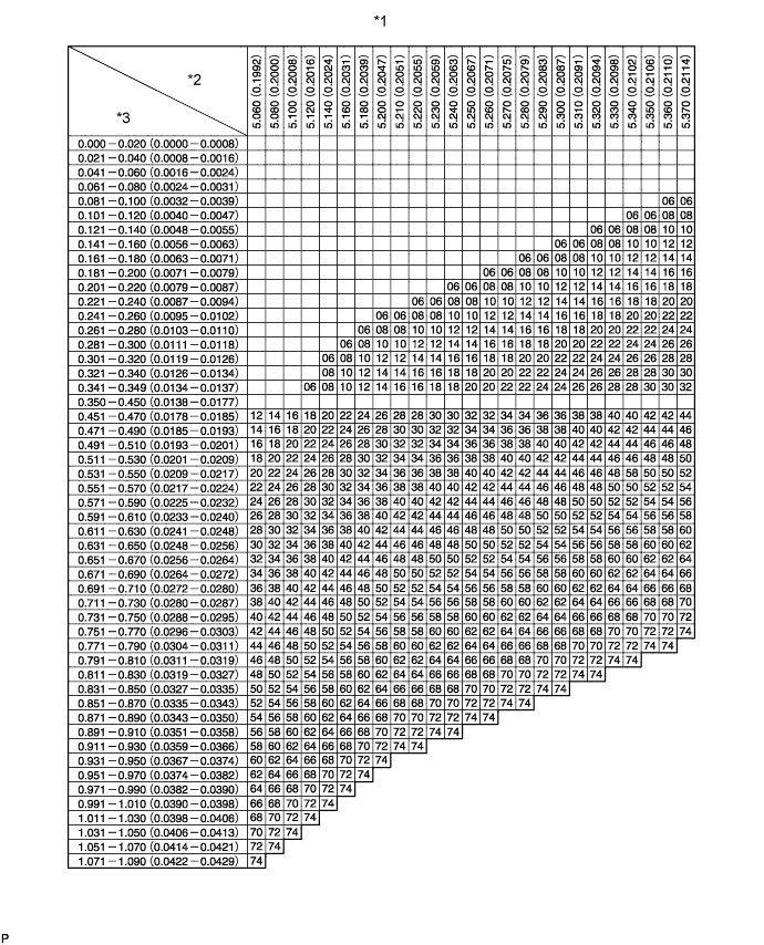
Text in Illustration *1 Valve Lifter Selection Chart (Exhaust) *2 Installed lifter thickness mm (in.) *3 Measured clearance mm (in.) - - 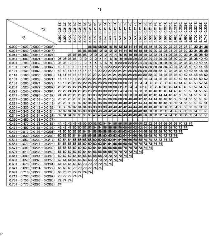
Text in Illustration *1 Valve Lifter Selection Chart (Exhaust) *2 Installed lifter thickness mm (in.) *3 Measured clearance mm (in.) - - Standard exhaust valve clearance (Cold) 0.35 to 0.45 mm (0.014 to 0.018 in.) EXAMPLE The 5.340 mm (0.2102 in.) lifter is installed, and the measured clearance is 0.480 mm (0.0189 in.). Replace the 5.340 mm (0.2102 in.) shim with a No. 42 lifter. New lifter thickness (mm (in.)) Shim No. Thickness Shim No. Thickness Shim No. Thickness 06 5.060 (0.1992) 30 5.300 (0.2087) 54 5.540 (0.2181) 08 5.080 (0.2000) 32 5.320 (0.2094) 56 5.560 (0.2189) 10 5.100 (0.2008) 34 5.340 (0.2102) 58 5.580 (0.2197) 12 5.120 (0.2016) 36 5.360 (0.2110) 60 5.600 (0.2205) 14 5.140 (0.2024) 38 5.380 (0.2118) 62 5.620 (0.2213) 16 5.160 (0.2031) 40 5.400 (0.2126) 64 5.640 (0.2220) 18 5.180 (0.2039) 42 5.420 (0.2134) 66 5.660 (0.2228) 20 5.200 (0.2047) 44 5.440 (0.2142) 68 5.680 (0.2236) 22 5.220 (0.2055) 46 5.460 (0.2150) 70 5.700 (0.2244) 24 5.240 (0.2063) 48 5.480 (0.2157) 72 5.720 (0.2252) 26 5.260 (0.2071) 50 5.500 (0.2165) 74 5.740 (0.2260) 28 5.280 (0.2079) 52 5.520 (0.2173) - - -
Install the camshaft Click here.
-
-
INSTALL GLOW PLUG ASSEMBLY
-
INSTALL INJECTOR ASSEMBLY
-
INSTALL EGR COOLER ASSEMBLY
-
INSTALL COMMON RAIL ASSEMBLY
-
ADD ENGINE OIL
-
Add fresh oil and install the oil filler cap.
Engine oil Item Oil Grade Oil Viscosity (SAE) w/ DPF
-
ACEA C2
(Using engine oil other than ACEA C2 may damage catalytic converter)
-
0W-30
-
5W-30
w/o DPF
-
G-DLD1, API CF-4, CF or ACEA B1
-
5W-30
-
10W-30
-
15W-40
-
20W-50
Capacity Item Fill Amount Drain and refill with oil filter change 7.0 liters (7.4 US qts, 6.2 Imp. qts) Drain and refill without oil filter change 6.8 liters (7.2 US qts, 6.0 Imp. qts) Dry fill 7.7 liters (8.1 US qts, 6.8 Imp. qts) -
-
-
ADD ENGINE COOLANT
-
Pour coolant into the radiator until it overflows.
Capacity Specification Capacity w/o Heater 9.8 liters (10.3 US qts, 8.6 Imp. qts) w/ Front Heater 10.7 liters (11.3 US qts, 9.4 Imp. qts) w/ Front and Rear Heater 11.5 liters (12.2 US qts, 10.1 Imp. qts) Note
Do not substitute plain water for engine coolant.
Tech Tips
-
Use of improper coolants may damage the engine cooling system.
-
Use only Toyota Super Long Life Coolant or similar high quality ethylene glycol based non-silicate, non-amine, non-nitrite, and non-borate coolant with long-life hybrid organic acid technology (coolant with long-life hybrid organic acid technology consists of a combination of low phosphates and organic acids).
-
-
Check the coolant level inside the radiator by squeezing the inlet and outlet radiator hoses several times by hand.
If the coolant level goes down, add coolant.
-
Install the radiator cap securely.
-
Slowly pour coolant into the radiator reservoir until it reaches the FULL line.
-
Warm up the engine until the thermostat opens.
-
While the thermostat is open, circulate the coolant for several minutes.
Tech Tips
The thermostat open timing can be confirmed by pressing the inlet radiator hose by hand, and checking when the engine coolant starts to flow inside the hose.
-
-
Maintain the engine speed at 2000 to 2500 rpm.
-
Squeeze the inlet and outlet radiator hoses several times by hand while warming up the engine to bleed the air.
CAUTION:
-
Wear protective gloves.
-
Be careful as the radiator hoses are hot.
-
Keep your hands away from the fan.
When squeezing the radiator hoses:
-
-
Stop the engine and wait until the coolant cools down.
-
Remove the radiator cap and check the coolant level inside the radiator.
-
If the coolant level is below the full level, repeat the operation until the coolant level remains at the full level.
-
Check the coolant level inside the radiator reservoir tank again.
If it is below the full level, add coolant.
-
-
INSPECT ENGINE OIL LEVEL
-
Warm up the engine, stop the engine and wait 5 minutes. The engine oil level should be between the dipstick low level mark and full level mark.
If low, check for leakage and add oil up to the full level mark.
Note
Do not fill engine oil above the full level mark.
-
-
INITIALIZATION AND REGISTRATION
-
INSPECT FOR ENGINE OIL LEAK
-
INSPECT FOR ENGINE COOLANT LEAK
-
INSPECT FOR EXHAUST GAS LEAK
-
INSPECT FOR FUEL LEAK