CYLINDER HEAD (w/ DPF) REMOVAL
Note
-
When replacing the injectors (including shuffling the injectors between the cylinders), common rail or cylinder head, it is necessary to replace the injection pipes with new ones.
-
When replacing the fuel supply pump, common rail, cylinder block, cylinder head, cylinder head gasket or timing gear case, it is necessary to replace the fuel inlet pipe with a new one.
-
After removing the injection pipes and fuel inlet pipe, clean them with a brush and compressed air.
-
DRAIN ENGINE OIL
-
Remove the oil filler cap.
-
Remove the drain plug from the oil pan and drain the engine oil into a container.
-
Clean the drain plug.
-
Install the drain plug with a new gasket.
- Torque:
- 34 N*m { 347 kgf*cm, 25 ft.*lbf }
-
-
DRAIN ENGINE COOLANT
CAUTION:
To avoid the danger of being burned, do not remove the radiator cap while the engine and radiator are still hot. Thermal expansion will cause hot engine coolant and steam to blow out from the radiator.
-
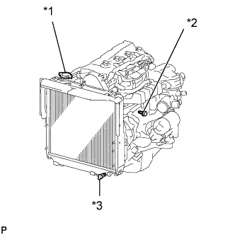
Text in Illustration *1 Radiator Cap *2 Engine Drain Plug *3 Radiator Drain Plug Loosen the radiator drain plug (on the radiator).
-
Remove the radiator cap.
-
Loosen the engine drain plug (on the oil cooler cover), and drain the coolant.
-
Drain the coolant from the reservoir tank.
-
Tighten the engine drain plug.
- Torque:
- 8.0 N*m { 82 kgf*cm, 71 in.*lbf }
-
-
REMOVE TIMING BELT
-
REMOVE CAMSHAFTS
-
REMOVE COMMON RAIL ASSEMBLY
-
REMOVE EGR COOLER ASSEMBLY
-
REMOVE INJECTOR ASSEMBLY
-
REMOVE GLOW PLUG ASSEMBLY
-
REMOVE ENGINE OIL LEVEL DIPSTICK GUIDE (for LHD)
-
Disconnect the wire harness from the wire harness clamp bracket.
-
Remove the 2 bolts and wire harness clamp bracket.
-
Remove the bolt and engine oil level dipstick guide.
-
Remove the O-ring from the engine oil level dipstick guide.
-
-
SEPARATE COOLER COMPRESSOR ASSEMBLY (w/ Air Conditioning System)
-
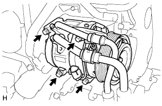
Remove the 4 bolts and disconnect the cooler compressor.
-
-
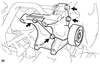
REMOVE NO. 1 COMPRESSOR MOUNTING BRACKET (w/ Air Conditioning System)
-
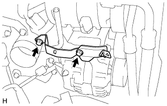
Remove the 4 bolts and No. 1 compressor mounting bracket.
-
-
REMOVE TURBOCHARGER SUB-ASSEMBLY
-
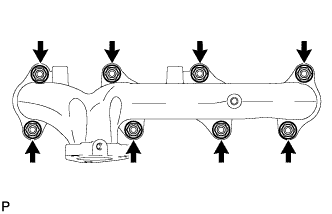
REMOVE EXHAUST MANIFOLD
-
Remove the 8 nuts, 8 plate washers, 8 collars and exhaust manifold.
-
-
REMOVE INTAKE MANIFOLD STAY
-
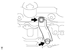
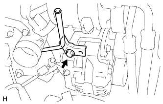
Remove the 2 bolts and intake manifold stay.
-
-
REMOVE NO. 1 INTAKE MANIFOLD INSULATOR
-
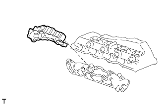
Remove the No. 1 intake manifold insulator from the intake manifold.
-
-
REMOVE INTAKE MANIFOLD
-
Remove the 7 bolts, 2 nuts and intake manifold.
-
Remove the gasket.
-
-
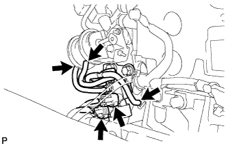
REMOVE VACUUM CONTROL VALVE SET
-
Remove the 2 connectors and 3 vacuum hoses.
-
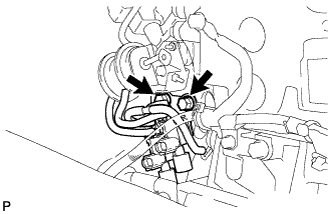
Remove the 2 bolts and vacuum control valve set.
-
-
REMOVE SWIRL CONTROL VALVE ASSEMBLY
-
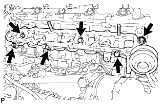
Remove the 4 bolts, 2 nuts and swirl control valve.
-
Remove the gasket.
-
-
REMOVE CYLINDER BLOCK INSULATOR
-
Remove the cylinder block insulator from the cylinder head.
-
-
REMOVE CYLINDER HEAD SUB-ASSEMBLY
-
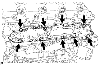
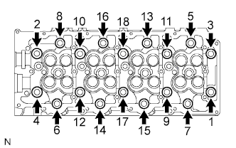
Uniformly loosen the 18 cylinder head bolts in several passes in the sequence shown in the illustration. Then remove the 18 cylinder head bolts and 18 washers.
Note
Head warpage or cracking could result from removing the bolts in an incorrect order.
-
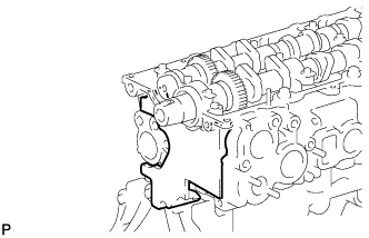
Lift the cylinder head from the dowels on the cylinder block and place the cylinder head on wooden blocks on a workbench.
Note
Be careful not to damage the contact surfaces of the cylinder head or cylinder block.
Tech Tips
If the cylinder head is difficult to lift, use a screwdriver to pry between the cylinder head and block.
-
-
REMOVE CYLINDER HEAD GASKET