CAMSHAFT (w/o DPF) INSTALLATION

-
INSTALL CAMSHAFTS
-
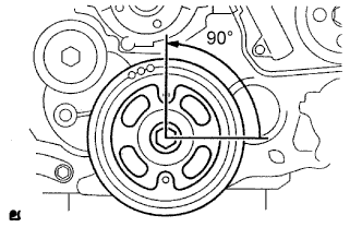
Using the crankshaft pulley bolt, set the No. 1 cylinder to 90° BTDC/compression.
Tech Tips
Set the No. 1 cylinder to 90° BTDC/compression to avoid interference with the piston top and valve head.
-
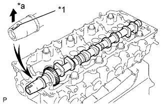
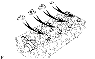
Install the camshaft.
-
Apply MP grease to the thrust portion of the camshaft.
-
Place the camshaft on the cylinder head, facing the key groove upward.
Text in Illustration *1 Key Groove *a Upward -
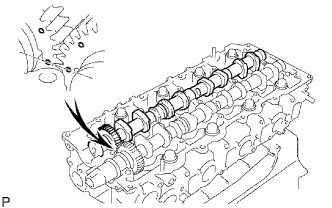
Align the timing marks (1 dot mark) of the camshaft drive and driven main gears, and set the No. 2 camshaft in place.
-
-
Remove any old packing (FIPG) material from the camshaft bearing cap.
-
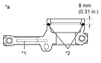
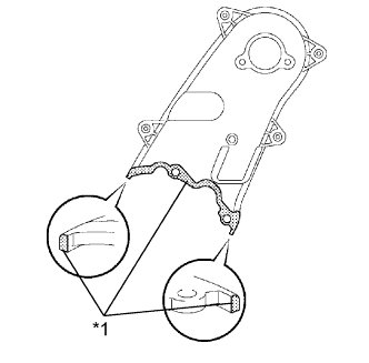
Apply seal packing to the specified areas shown in the illustration.
Text in Illustration *1 Oil Passage *2 Seal Packing *a Seal Diameter: 4 mm Seal packing Toyota Genuine Seal Packing Black, Three Bond 1207B or equivalent Standard seal diameter 4 mm (0.16 in.) Note
-
Do not allow FIPG to come into contact with the oil passage of the bearing cap.
-
After applying FIPG, install the camshaft bearing caps within 3 minutes and tighten the bolts within 15 minutes.
-
Do not start the engine for at least 2 hours after the installation.
-
Install the 5 bearing caps in the proper locations.
-
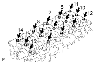
Apply a light coat of engine oil to the threads and under the heads of the bearing cap bolts.
-
Install and uniformly tighten the 15 bearing cap bolts in several passes in the sequence shown in the illustration.
- Torque:
- 19 N*m { 194 kgf*cm, 14 ft.*lbf }
-
-
-
INSTALL CAMSHAFT SETTING OIL SEAL
-
Apply MP grease to the lip of a new oil seal.
-
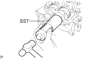
Using SST and a hammer, tap in the oil seal until its surface is flush with the oil seal retainer edge.
- SST
- 09608-06041
-
-
SET NO. 1 CYLINDER TO TDC / COMPRESSION
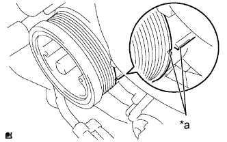
Text in Illustration *a Alignment Mark
-
Align the alignment mark of the crankshaft pulley and timing gear case cover by rotating the crankshaft clockwise.
Tech Tips
Make sure that both cam-noses (intake side and exhaust side) of the No. 1 cylinder face upward.
-
-
INSPECT VALVE CLEARANCE
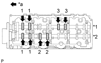
Text in Illustration *1 Exhaust *2 Intake *a Front
-
Check only the valves indicated.
-
Using a feeler gauge, measure the clearance between the valve lifter and camshaft.
Standard valve clearance (Cold) Intake Exhaust 0.20 to 0.30 mm (0.008 to 0.012 in.) 0.35 to 0.45 mm (0.014 to 0.018 in.) Write down the valve clearance measurements that are not within the specified range. These measurements will be used later to determine the size of the adjustment shim to be installed.
-
-
Turn the crankshaft 360° to set the No. 4 cylinder to TDC / compression.
-
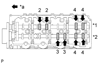
Text in Illustration *1 Exhaust *2 Intake *a Front Check only the valves indicated.
-
Using a feeler gauge, measure the clearance between the valve lifter and camshaft.
Standard valve clearance Intake Exhaust 0.20 to 0.30 mm (0.008 to 0.012 in.) 0.35 to 0.45 mm (0.014 to 0.018 in.) Write down the valve clearance measurements that are not within the specified range. These measurements will be used later to determine the size of the adjustment shim to be installed.
-
-
-
ADJUST VALVE CLEARANCE
-
Remove the camshafts Click here.
-
Remove the 8 valve lifters.
-
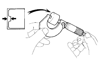
Using a micrometer, measure the thickness of the removed lifter.
-
Calculate the thickness of a new lifter so that the valve clearance comes within the specified value.
A B C New lifter thickness Used lifter thickness Measured valve clearance New lifter thickness Intake A = B + (C - 0.25 mm (0.0098 in.)) Exhaust A = B + (C - 0.40 mm (0.00158 in.)) -
Select a new lifter with a thickness as close as possible to the calculated values.
Tech Tips
Valve lifters are available in 35 sizes in increments of 0.020 mm (0.0008 in.), from 5.060 mm (0.1992 in.) to 5.740 mm (0.2260 in.).
-
Install the selected valve lifter.
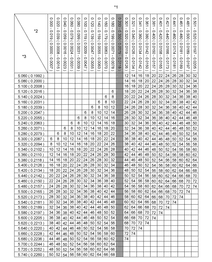
Text in Illustration *1 Intake Valve Lifter Chart (1/2) *2 Measured Clearance mm (in.) *3 Installed Lifter Thickness mm (in.) - - 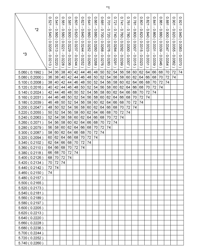
Text in Illustration *1 Intake Valve Lifter Chart (2/2) *2 Measured Clearance mm (in.) *3 Installed Lifter Thickness mm (in.) - - Standard intake valve clearance (Cold) 0.20 to 0.30 mm (0.008 to 0.012 in.) EXAMPLE The 5.250 mm (0.2067 in.) lifter is installed, and the measured clearance is 0.400 mm (0.0158 in.). Replace the 5.250 mm (0.2067 in.) shim with a No. 40 lifter. New lifter thickness (mm (in.)) Shim No. Thickness Shim No. Thickness Shim No. Thickness 06 5.060 (0.1992) 30 5.300 (0.2087) 54 5.540 (0.2181) 08 5.080 (0.2000) 32 5.320 (0.2094) 56 5.560 (0.2189) 10 5.100 (0.2008) 34 5.340 (0.2102) 58 5.580 (0.2197) 12 5.120 (0.2016) 36 5.360 (0.2110) 60 5.600 (0.2205) 14 5.140 (0.2024) 38 5.380 (0.2118) 62 5.620 (0.2213) 16 5.160 (0.2031) 40 5.400 (0.2126) 64 5.640 (0.2220) 18 5.180 (0.2039) 42 5.420 (0.2134) 66 5.660 (0.2228) 20 5.200 (0.2047) 44 5.440 (0.2142) 68 5.680 (0.2236) 22 5.220 (0.2055) 46 5.460 (0.2150) 70 5.700 (0.2244) 24 5.240 (0.2063) 48 5.480 (0.2157) 72 5.720 (0.2252) 26 5.260 (0.2071) 50 5.500 (0.2165) 74 5.740 (0.2260) 28 5.280 (0.2079) 52 5.520 (0.2173) - - 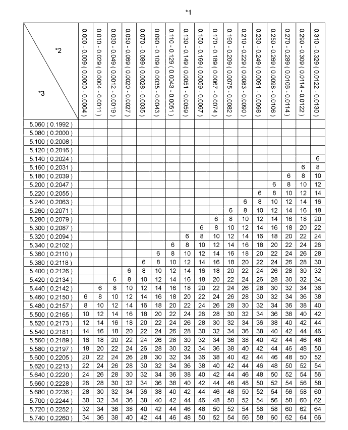
Text in Illustration *1 Exhaust Valve Lifter Chart (1/3) *2 Measured Clearance mm (in.) *3 Installed Lifter Thickness mm (in.) - - 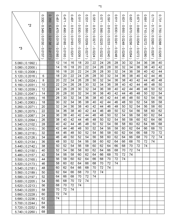
Text in Illustration *1 Exhaust Valve Lifter Chart (2/3) *2 Measured Clearance mm (in.) *3 Installed Lifter Thickness mm (in.) - - 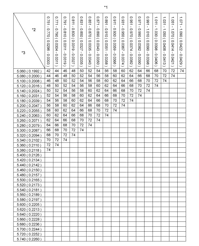
Text in Illustration *1 Exhaust Valve Lifter Chart (3/3) *2 Measured Clearance mm (in.) *3 Installed Lifter Thickness mm (in.) - - Standard exhaust valve clearance (Cold) 0.35 to 0.45 mm (0.014 to 0.018 in.) EXAMPLE The 5.340 mm (0.2102 in.) lifter is installed, and the measured clearance is 0.480 mm (0.0189 in.). Replace the 5.340 mm (0.2102 in.) shim with a No. 42 lifter. New lifter thickness (mm (in.)) Shim No. Thickness Shim No. Thickness Shim No. Thickness 06 5.060 (0.1992) 30 5.300 (0.2087) 54 5.540 (0.2181) 08 5.080 (0.2000) 32 5.320 (0.2094) 56 5.560 (0.2189) 10 5.100 (0.2008) 34 5.340 (0.2102) 58 5.580 (0.2197) 12 5.120 (0.2016) 36 5.360 (0.2110) 60 5.600 (0.2205) 14 5.140 (0.2024) 38 5.380 (0.2118) 62 5.620 (0.2213) 16 5.160 (0.2031) 40 5.400 (0.2126) 64 5.640 (0.2220) 18 5.180 (0.2039) 42 5.420 (0.2134) 66 5.660 (0.2228) 20 5.200 (0.2047) 44 5.440 (0.2142) 68 5.680 (0.2236) 22 5.220 (0.2055) 46 5.460 (0.2150) 70 5.700 (0.2244) 24 5.240 (0.2063) 48 5.480 (0.2157) 72 5.720 (0.2252) 26 5.260 (0.2071) 50 5.500 (0.2165) 74 5.740 (0.2260) 28 5.280 (0.2079) 52 5.520 (0.2173) - - -
Install the camshaft Click here.
-
-
INSTALL NO. 2 TIMING BELT COVER
Text in Illustration *1 Seal Packing
-
Apply seal packing (FIPG) to the specified areas shown in the illustration.
Seal Packing Toyota Genuine Seal Packing Black, Three Bond 1207B or equivalent Note
After applying FIPG, install the No. 2 timing belt cover within 3 minutes and tighten the bolts and nut within 15 minutes.
-
Clean the bolts and their holes.
-
Apply adhesive to 2 or 3 threads at the end of each of the 4 bolts.
Adhesive Toyota Genuine Adhesive 1324, Three Bond 1324 or equivalent -
Install the No. 2 timing belt cover with the 4 bolts and nut.
- Torque:
- 10 N*m { 102 kgf*cm, 7 ft.*lbf }
-
-
INSTALL CAMSHAFT TIMING PULLEY
-
Install the camshaft timing pulley.
-
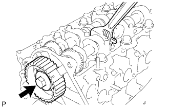
Fasten the bolt of the camshaft timing pulley while holding the camshaft with a wrench.
- Torque:
- 98 N*m { 1000 kgf*cm, 72 ft.*lbf }
-
-
INSTALL INJECTOR ASSEMBLY
Refer to the procedures up to "INSTALL INJECTOR ASSEMBLY" Click here.
-
INSTALL TIMING BELT
Refer to the procedures up to "INSTALL TIMING BELT" Click here.