CAMSHAFT (w/o DPF) INSPECTION
-
INSPECT CAMSHAFT
-
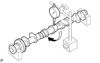
Inspect the circle runout.
-
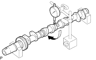
Place the camshaft on V-blocks.
-
Using a dial indicator, measure the circle runout.
Maximum circle runout 0.03 mm (0.0012 in.) If the circle runout is greater than the maximum, replace the camshaft.
-
-
Inspect the cam lobe height.
-
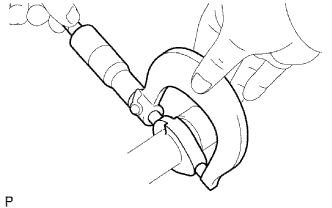
Using a micrometer, measure the cam lobe height.
Standard cam lobe height 47.180 to 47.280 mm (1.8575 to 1.8614 in.) Minimum cam lobe height 46.760 mm (1.8409 in.) If the cam lobe height is less than the minimum, replace the camshaft.
-
-
Inspect the journal diameter of the camshaft.
-
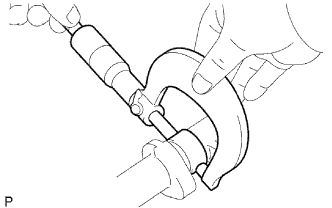
Using a micrometer, measure the journal diameter of the camshaft bearing.
Standard journal diameter 27.969 to 27.985 mm (1.1011 to 1.1018 in.) If the journal diameters is not as specified, check the oil clearance.
-
-
Check the oil clearance.
-
Clean the bearing caps and journals.
-
Check the bearings for flaking and scoring.
If the bearings are damaged, replace the bearing caps and cylinder head as a set.
-
Install the bearings to the bearing caps and cylinder head.
-
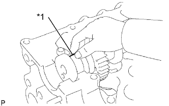
Place the camshaft on the cylinder head.
-
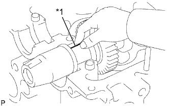
Lay a strip of Plastigage across each of the journals.
Text in Illustration *1 Plastigage -
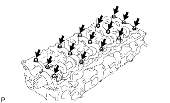
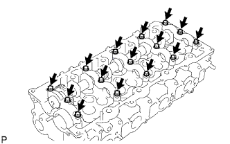
Install the bearing caps.
Note
Do not turn the camshaft.
-
Remove the bearing caps.
-
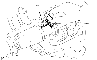
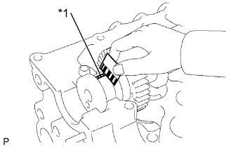
Text in Illustration *1 Plastigage Measure the Plastigage at its widest point.
Standard oil clearance 0.025 to 0.062 mm (0.0010 to 0.0024 in.) Maximum oil clearance 0.10 mm (0.0039 in.) If the oil clearance is greater than the maximum, replace the camshaft. If necessary, replace the bearing caps and cylinder head as a set.
-
Completely remove the Plastigage.
-
Remove the camshaft. Click here
-
-
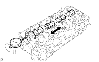
Check the thrust clearance.
-
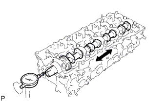
Install the camshaft. Click here
-
Using a dial indicator, measure the thrust clearance while moving the camshaft back and forth.
Standard thrust clearance 0.035 to 0.185 mm (0.0014 to 0.0073 in.) Maximum thrust clearance 0.25 mm (0.0098 in.) If the thrust clearance is greater than the maximum, replace the camshaft. If necessary, replace the bearing caps and cylinder head as a set.
-
-
Using a dial indicator, measure the backlash.
-
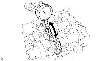
Install the 2 camshafts.
-
Using a dial indicator, measure the backlash.
Standard backlash 0.035 to 0.089 mm (0.0014 to 0.0035 in.) Maximum backlash 0.189 mm (0.0074 in.) If the backlash is greater than the maximum, replace the camshaft.
-
Remove the 2 camshafts. Click here
-
-
-
INSPECT NO.2 CAMSHAFT
-
Inspect the circle runout.
-
Place the camshaft on V-blocks.
-
Using a dial indicator, measure the circle runout.
Maximum circle runout 0.03 mm (0.0012 in.) If the circle runout is greater than the maximum, replace the camshaft.
-
-
Inspect the cam lobe height.
-
Using a micrometer, measure the cam lobe height.
Standard cam lobe height 48.071 to 48.171 mm (1.8925 to 1.8965 in.) Maximum cam lobe height 47.920 mm (1.8866 in.) If the cam lobe height is less than the minimum, replace the camshaft.
-
-
Inspect the journal diameter of the camshaft.
-
Using a micrometer, measure the journal diameter of the camshaft bearing.
Standard journal diameter 27.969 to 27.985 mm (1.1011 to 1.1018 in.) If the journal diameters is not as specified, check the oil clearance.
-
-
Check the oil clearance.
-
Clean the bearing caps and journals.
-
Check the bearings for flaking and scoring.
If the bearings are damaged, replace the bearing caps and cylinder head as a set.
-
Install the bearings to the bearing caps and cylinder head.
-
Place the camshaft on the cylinder head.
-
Lay a strip of Plastigage across each of the journals.
Text in Illustration *1 Plastigage -
Install the bearing caps.
Note
Do not turn the camshaft.
-
Remove the bearing caps.
-
Text in Illustration *1 Plastigage Measure the Plastigage at its widest point.
Standard oil clearance 0.025 to 0.062 mm (0.0010 to 0.0024 in.) Maximum oil clearance 0.10 mm (0.0039 in.) If the oil clearance is greater than the maximum, replace the camshaft. If necessary, replace the bearing caps and cylinder head as a set.
-
Completely remove the Plastigage.
-
Remove the camshaft. Click here
-
-
Check the thrust clearance.
-
Install the camshaft. Click here
-
Using a dial indicator, measure the thrust clearance while moving the camshaft back and forth.
Standard thrust clearance 0.035 to 0.185 mm (0.0014 to 0.0073 in.) Maximum thrust clearance 0.25 mm (0.0098 in.) If the thrust clearance is greater than the maximum, replace the camshaft. If necessary, replace the bearing caps and cylinder head as a set.
-
Remove the camshafts. Click here
-
-