ENGINE (w/ DPF) ON-VEHICLE INSPECTION

-
INSPECT ENGINE COOLANT QUALITY
-
Remove the radiator cap.
CAUTION:
To avoid the danger of being burned, do not remove the radiator cap while the engine and radiator are still hot. Thermal expansion will cause hot engine coolant and steam to blow out from the radiator.
-
Check for any excessive deposits of rust or scale around the radiator cap and radiator filler hole; the coolant should be free of oil.
If excessively dirty, replace the coolant.
-
Reinstall the radiator cap.
-
-
INSPECT ENGINE OIL
-
Check the oil quality.
-
Check the oil for deterioration, water contamination, discoloration or thinning.
-
-
Check the oil level.
-
Warm up the engine, stop the engine and wait 5 minutes.
-
Check that the oil level is between the upper level and lower level of the oil level dipstick.
If the oil level is low, check for leakage and add oil up to the upper level of the oil level dipstick.
-
-
-
INSPECT BATTERY
CAUTION:
If the battery is weak or if the engine is difficult to start, perform the following procedures.
-
Check the battery for damage and deformation. If severe damage, deformation, or leakage is found, replace the battery.
-
Check the electrolyte level of each cell.
-
For maintenance-free batteries:
-
If the electrolyte level is below the lower line, replace the battery.
-
If the electrolyte level is above the lower line, check the battery voltage when cranking the engine.
-
If the voltage is less than 9.6 V, recharge or replace the battery.
Tech Tips
Before checking the battery voltage, turn off all the electrical systems (headlights, blower motor, rear defogger, etc.).
-
-
For non-maintenance-free batteries:
-
If the electrolyte level is below the lower line, add distilled water to each cell. Then, recharge the battery and check the electrolyte gravity.
Standard gravity 1.25 to 1.29 at 20°C (68°F) If the electrolyte level is above the lower line, check the battery voltage when cranking the engine. If the voltage is less than 9.6 V, recharge or replace the battery.
Tech Tips
Before checking the battery voltage, turn off all electrical systems (headlights, blower motor, rear defogger, etc.).
-
-
-
-
INSPECT AIR CLEANER FILTER ELEMENT SUB-ASSEMBLY
-
Remove the air cleaner filter element sub-assembly.
-
Visually check that there is no dirt, blockage, or damage to the air cleaner filter element.
Tech Tips
-
If there is any dirt or a blockage in the air cleaner filter element, clean it with compressed air.
-
If any dirt or a blockage remains even after cleaning the air cleaner filter element with compressed air, replace it.
-
-
-
CHECK ENGINE IDLING SPEED AND MAXIMUM SPEED
Note
Turn all the electrical systems OFF.
-
Warm up and stop the engine.
-
When using the intelligent tester:
-
Connect the intelligent tester to the DLC3.
-
Turn the ignition switch to ON.
-
Select the following menu items:
Powertrain / Engine and ECT / Data List / Engine Speed.
Tech Tips
Refer to the intelligent tester operator's manual for further information regarding the selection of Data List.
-
Inspect the engine idling speed.
Idling speed 700 to 800 rpm -
Fully depress the accelerator pedal.
-
Check the maximum speed.
Maximum speed 4500 to 4700 rpm -
Turn the ignition switch to OFF.
-
Disconnect the intelligent tester from the DLC3.
-
-
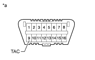
Text in Illustration *a Front view of DLC3 When not using the intelligent tester:
-
Install SST to terminal 9 (TAC) of DLC3, then connect a tachometer.
- SST
- 09843-18040
Note
Examine the terminal numbers before connecting them. Connecting the wrong terminals can damage the engine.
-
Turn the ignition switch to ON.
-
Inspect the engine idling speed.
Idling speed 700 to 800 rpm -
Fully depress the accelerator pedal.
-
Check the maximum speed.
Maximum speed 4500 to 4700 rpm -
Turn the ignition switch to OFF.
-
disconnect the tachometer.
-
Remove SST from terminal 9.
-
-
-
INSPECT COMPRESSION
-
Warm up and stop the engine.
-
Remove the common rail Click here.
-
Remove the No. 1 intake manifold insulator.
-
Reinstall the common rail Click here.
-
Remove the 4 glow plugs Click here.
Note
In order to avoid shorting the circuit of the wire harness connected to the glow plug No. 1 connector, wrap vinyl tape around the wire harness terminal portion.
-
Disconnect all the connectors from the 4 injectors.
-
Connect the cable to negative battery terminal.
- Torque:
- 6.4 N*m { 65 kgf*cm, 57 in.*lbf }
-
Crank the engine to remove foreign objects before measuring the compression.
-
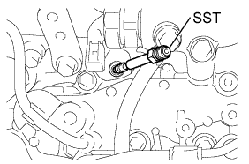
Install SST into the glow plug hole.
- SST
- 09992-00026 ( 09992-00121 )
- Torque:
- 13 N*m { 133 kgf*cm, 10 ft.*lbf }
-
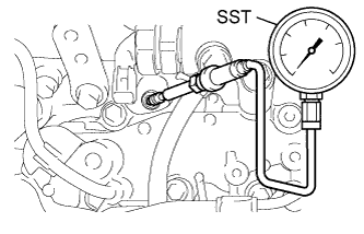
Connect a compression gauge to SST.
- SST
- 09992-00026 ( 09992-00211 )
-
While cranking the engine, measure the compression pressure.
Standard pressure 2000 kPa (20.1 kgf/cm2, 290 psi) Minimum pressure 1630 kPa (16.6 kgf/cm2, 236 psi) Difference between each cylinder 500 kPa (5.0 kgf/cm2, 71 psi) or less Note
-
Use a fully-charged battery so that the engine speed can be increased to 250 rpm or more.
-
Inspect the other cylinders in the same way.
-
Measure the compression pressure in as short a time as possible.
If the cylinder compression is low, pour a light coat of engine oil into the cylinder through the glow plug hole, then inspect it again.
Tech Tips
-
If adding oil increases the compression, the piston rings and/or cylinder bore may be worn or damaged.
-
If the pressure stays low, a valve may be stuck or seated improperly, or there may be leakage from the gasket.
-
-
Remove the compression gauge and SST.
-
Disconnect the cable from the negative battery terminal.
-
Connect all the connectors to the 4 injectors.
-
Install the 4 glow plugs Click here.
-
Remove the common rail Click here.
-
Reinstall the No. 1 intake manifold insulator.
-
Install the common rail Click here.
-