ECD SYSTEM TC and CG Terminal Circuit
DESCRIPTION
-
DESCRIPTION
-
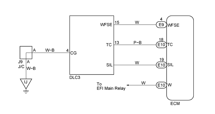
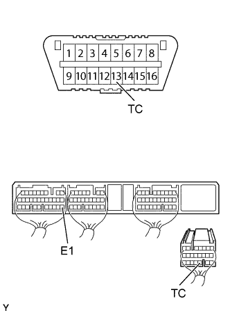
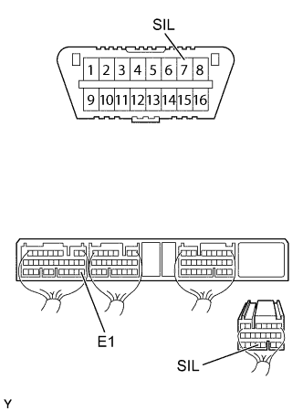
Terminals TC and CG are located in the DLC3.
The DLC3 is located under the finish lower panel. When terminals TC and CG are connected, DTC in normal mode or test mode can be read from the check engine warning light in the combination meter. Also, terminal SIL is located in the DLC3. This terminal is used by the M-OBD communication with intelligent tester.
-
WIRING DIAGRAM
INSPECTION PROCEDURE
PROCEDURE
-
CHECK ENGINE WARNING LIGHT CONDITION
-
Turn the ignition switch ON.
-
Using SST, connect terminals TC and CG of the DLC3.
- SST
- 09843-18040
-
Check the engine warning light condition.
Check engine warning light Blinking Tech Tips
If this inspection OK and there is no intelligent tester, do not need to do the following steps and this circuit is OK. Proceed to next circuit inspection shown on problem symptom table Click here.
OK 
READ OUTPUT DTC OF INTELLIGENT TESTER (INCLUDING NORMAL DTC) Click here
NG 
-
-
CHECK DLC3 (CHECK VOLTAGE)
-
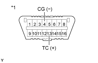
Text in Illustration *1 DLC3 Turn the ignition switch ON.
-
Check the voltage between terminals of the DLC3 as shown in the table and illustration.
Voltage Terminal
(Positive terminal ←→ Negative terminal)
Voltage TC (13) ←→ CG (4) 9 - 14 V
OK
CHECK ECM (CHECK VOLTAGE) Click here
NG
-
-
CHECK DLC3 (CHECK CONTINUITY)
-
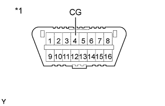
Text in Illustration *1 DLC3 Check the continuity between terminals of the DLC3 as shown in the illustration and table.
Continuity (Check for open) Terminal
(DLC3 ←→ Body ground)
Standard CG (4) ←→ Body ground continuity
NG 
REPAIR OR REPLACE HARNESS AND CONNECTOR
OK
-
-
CHECK WIRE HARNESS (ECM - DLC3)
-
Disconnect the ECM (E10) connector.
-
Check the continuity between terminals of the DLC3 and ECM connectors as shown in the illustration and table.
Continuity (Check for open) Terminal
(DLC3 ←→ ECM)
Standard TC (13) ←→ TC (E10-18) Continuity Continuity (Check for short) Terminal
(DLC3 ←→ ECM(Ground))
Standard TC (13) ←→ E1 (E7-22) No continuity
NG
REPAIR OR REPLACE HARNESS AND CONNECTOR
OK
-
-
CHECK ECM (CHECK VOLTAGE)
-
Turn the ignition switch ON.
-
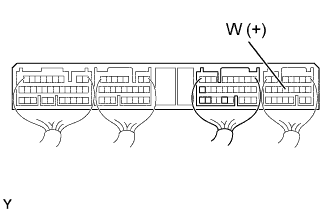
Check the voltage between terminals of the ECM as shown in the table and illustration.
Voltage Terminal
(Positive terminal ←→ Negative terminal)
Voltage W (E10-12) ←→ Body ground 9 - 14 V
OK
CHECK AND REPLACE ECM
NG
-
-
CHECK BULB (ENGINE WARNING LIGHT)
NG
REPLACE BULB
OK
-
CHECK WIRE HARNESS (ECM - COMBINATION METER)
-
Disconnect the combination meter (C9) connector.
-
Disconnect the ECM (E10) connector.
-
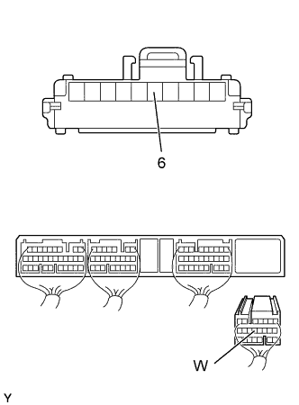
Check the continuity between terminals of the combination meter and ECM connectors as shown in the illustration and table.
Continuity (Check for open) Terminal
(Combination meter ←→ ECM)
Standard C9-6 ←→ W (E10-12) Continuity Continuity (Check for short) Terminal
(Combination meter ←→ ECM)
Standard W (E10-12) ←→ E1 (E7-22) No continuity
NG
REPAIR OR REPLACE HARNESS AND CONNECTOR
OK
-
-
READ OUTPUT DTC OF INTELLIGENT TESTER (INCLUDING NORMAL DTC)
NG
PROCEED TO NEXT CIRCUIT INSPECTION SHOWN ON PROBLEM SYMPTOM TABLE Click here
OK
-
CHECK DLC3 (CHECK VOLTAGE)
-
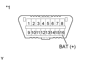
Text in Illustration *1 DLC3 Turn the ignition switch ON.
-
Check the voltage between terminals of the DLC3 as shown in the table and illustration.
Voltage Terminal
(Positive terminal ←→ Negative terminal)
Voltage BAT (16) ←→ Body ground 9 - 14 V
NG
REPAIR OR REPLACE HARNESS AND CONNECTOR
OK
-
-
CHECK WIRE HARNESS (ECM - DLC3)
-
Disconnect the ECM (E10) connector.
-
Check the continuity between terminals of the DLC3 and ECM connectors as shown in the illustration and table.
Continuity (Check for open) Terminal
(DLC3 ←→ ECM)
Standard SIL (7) ←→ SIL (E10-19) Continuity Continuity (Check for short) Terminal
(DLC3 ←→ ECM (Ground))
Standard SIL (7) ←→ E1 (E7-22) No continuity
NG
REPAIR OR REPLACE HARNESS AND CONNECTOR
OK 
REPAIR OR REPLACE ECM Click here
-