ECD SYSTEM ECU Power Source Circuit
DESCRIPTION
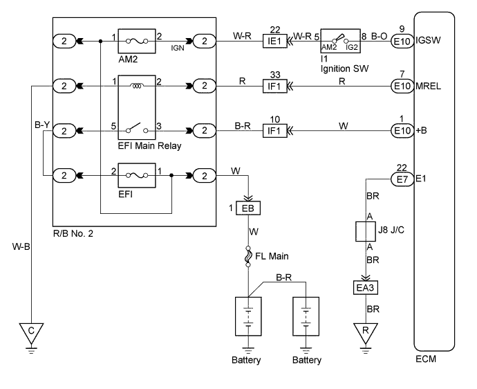
When the ignition switch is turned ON, battery positive voltage is applied to the coil, closing the contacts of the EFI relay (Marking: EFI) and supplying power to the terminal +B of the ECM.
WIRING DIAGRAM
INSPECTION PROCEDURE
PROCEDURE
-
CHECK ECM (CHECK VOLTAGE)
-
Turn the ignition switch ON.
-
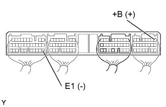
Check the voltage between terminals of the ECM connector as shown in the table and illustration.
Voltage Terminal
(Positive terminal ←→ Negative terminal)
Voltage +B (E10-1) ←→ E1 (E7-22) 9 - 14 V
OK 
PROCEED TO NEXT CIRCUIT INSPECTION SHOWN ON PROBLEM SYMPTOM TABLE Click here
NG 
-
-
CHECK WIRE HARNESS (ECM - BODY GROUND)
-
Disconnect the ECM (E7) connector.
-
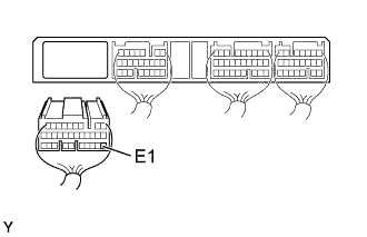
Check the continuity between terminals of the ECM connector as shown in the illustration and table.
Continuity (Check for open) Terminal
(ECM ←→ ECM(Ground))
Standard E1 (E7-22) ←→ Body ground Continuity
(1 Ω or less)
NG
REPAIR OR REPLACE HARNESS AND CONNECTOR
OK
-
-
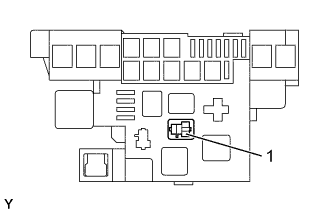
CHECK MAIN RELAY
-
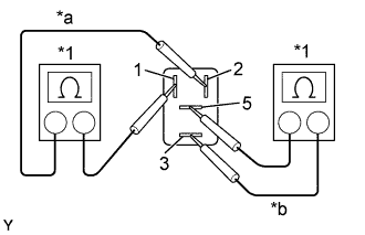
Text in Illustration *1 Ohmmeter *a Continuity *b No Continuity Remove the main relay from the relay block No. 2.
-
Inspect the relay continuity.
-
Using an ohmmeter, check that there is continuity between terminals 1 and 2.
-
Check that there is no continuity between terminals 3 and 5.
-
-
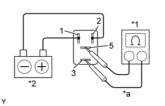
Text in Illustration *1 Ohmmeter *2 Battery *a Continuity Inspect the relay operation.
-
Apply battery voltage across terminals 1 and 2.
-
Using an ohmmeter, check that there is continuity between terminals 3 and 5.
-
NG
REPLACE MAIN RELAY
OK
-
-
CHECK FUSE (EFI FUSE)
-
Remove the EFI fuse from the R/B No. 2.
-
Check the continuity of the EFI fuse.
Result Continuity -
Check for short in all harness and components connected to the EFI fuse.
NG
REPLACE FUSE
OK
-
-
CHECK WIRE HARNESS (ECM - EFI MAIN RELAY) (a) (EFI MAIN RELAY - BATTERY) (b)
-
Check for open and short in harness and connector between the ECM and EFI main relay.
-
Remove the EFI main relay.
-
Disconnect the ECM (E10) connector.
-
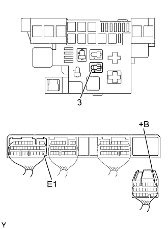
Check the continuity between terminals of the EFI main relay (3) of the R/B No. 2 and ECM connector as shown in the illustration and table.
Continuity (Check for open) Terminal
(EFI main relay of R/B No. 2 ←→ ECM)
Standard 3 ←→ +B (E10-1) Continuity Continuity (Check for short) Terminal
(ECM ←→ ECM(Ground))
Standard +B (E10-1) ←→ E1 (E7-22) No continuity
-
-
Check for open in harness and connector between the EFI main relay and battery.
-
Remove the EFI main relay.
-
Disconnect the battery positive terminal.
-
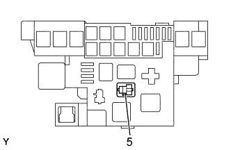
Check continuity between the terminals EFI main relay (5) of R/B No. 2 and battery positive terminal wire.
Continuity (Check for open) Terminal
(EFI main relay of R/B No. 2 ←→ Battery)
Standard 5 ←→ Battery positive terminal Continuity
-
NG
REPAIR OR REPLACE HARNESS AND CONNECTOR
OK
-
-
CHECK ECM (CHECK VOLTAGE)
-
Turn the ignition switch ON.
-
Check the voltage between terminals of the ECM connectors as shown in the table and illustration.
Voltage Terminal
(Positive terminal ←→ Negative terminal)
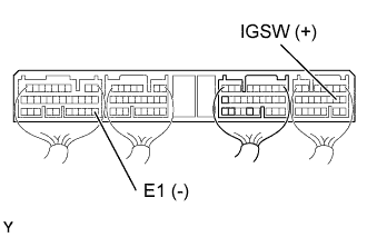
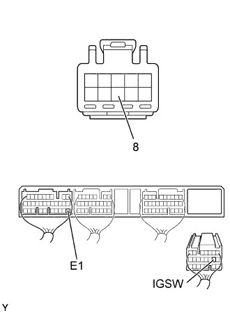
Voltage IGSW (E10-9) ←→ E1 (E8-22) 9 - 14 V
OK 
CHECK ECM (CHECK VOLTAGE) Click here
NG
-
-
CHECK IGNITION OR STARTER SWITCH ASSEMBLY
-
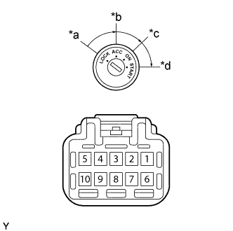
Text in Illustration *a LOCK *b ACC *c ON *d START Remove the lower finish panel.
-
Disconnect the ignition switch connector.
-
Check the continuity between the terminals shown below.
Continuity Switch position Terminal No. to continuity LOCK - - ACC 4 ←→ 9 - ON 4 ←→ 9 ←→ 10 5 ←→ 8 START 3 ←→ 9 ←→ 10 5 ←→ 8
NG
REPLACE IGNITION OR STARTER SWITCH ASSEMBLY
OK
-
-
CHECK WIRE HARNESS (ECM - IGNITION SWITCH)
-
Disconnect the ignition switch connector.
-
Disconnect the ECM (E10) connector.
-
Check the continuity between terminals of the ignition switch and ECM connectors as shown in the illustration and table.
Continuity (Check for open) Terminal
(Ignition switch ←→ ECM)
Standard IG2 (8) ←→ IGSW (E10-9) Continuity Continuity (Check for short) Terminal
(ECM ←→ ECM(Ground))
Standard IGSW (E10-9) ←→ E1 (E7-22) No continuity
NG
REPAIR OR REPLACE HARNESS AND CONNECTOR
OK
-
-
CHECK ECM (CHECK VOLTAGE)
-
Turn the ignition switch ON.
-
Check the voltage between terminals of the ECM connectors as shown in the table and illustration.
Voltage Terminal
(Positive terminal ←→ Negative terminal)
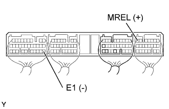
Voltage MREL (E10-7) ←→ E1 (E7-22) 9 - 14 V
OK
CHECK AND REPLACE ECM Click here
NG
-
-
CHECK HARNESS AND CONNECTOR (ECM - EFI MAIN RELAY) (a) (EFI MAIN RELAY - BODY GROUND) (b)
-
Check for open and short in harness and connector between the ECM and EFI main relay.
-
Remove the EFI main relay.
-
Disconnect the ECM (E10) connector.
-
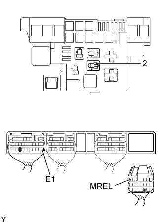
Check the continuity between terminals of the EFI main relay (2) of the R/B No. 2 and ECM connector as shown in the illustration and table.
Continuity (Check for open) Terminal
(EFI main relay of R/B No. 2 ←→ ECM)
Standard 2 ←→ MREL (E10-7) Continuity Continuity (Check for short) Terminal
(ECM ←→ ECM(Ground))
Standard MREL (E10-7) ←→ E1 (E7-22) No continuity
-
-
Check for open and short in harness and connector between the EFI main relay and body ground.
-
Check the continuity between terminals of the EFI main relay (1) of the R/B No. 2 and body ground as shown in the illustration and table.
Continuity (Check for open) Terminal
(EFI main relay of R/B No. 2 ←→ Body ground)
Standard 1 ←→ Body ground Continuity
-
NG
REPAIR OR REPLACE HARNESS AND CONNECTOR
OK 
REPAIR OR REPLACE ENGINE ROOM RELAY BLOCK
-