ECD SYSTEM EGR Control Circuit
DESCRIPTION
-
DESCRIPTION
-
The EGR system recirculates exhaust gas, which is controlled to the proper quantity to suit the driving conditions into the intake air mixture to slow down combustion, reduce the combustion temperature and reduce NOx emissions,
The lift amount of EGR valve is controlled by the vacuum which is regulated by the E-VRV operated by the ECM.
If even one of the following conditions is fulfilled, the VSV is turned ON by a signal from the ECM. This results in atmospheric air acting on the EGR valve, closing the EGR valve and shutting off the exhaust gas (EGR cut-off).
-
Under the following conditions, EGR is cut to maintain driveability.
-
Before the engine is warmed up
-
Engine speed over 4,000 rpm
-
-
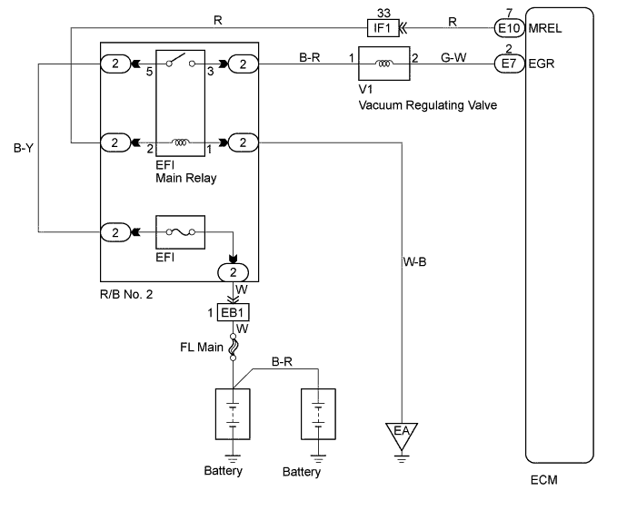
WIRING DIAGRAM
INSPECTION PROCEDURE
When not using the intelligent tester go to step 8.
PROCEDURE
-
CHECK THE CONNECTION OF VACUUM HOSE
NG 
REPAIR OR REPLACE VACUUM HOSE
OK 
-
CHECK VACUUM
-
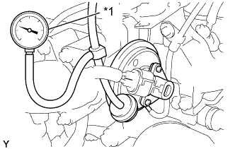
Text in Illustration *1 Vacuum Gage Using a 3-way connector, connect a vacuum gauge to the hose between the VSV and EGR valve.
-
Warm up the engine to above 80°C (176°F).
-
Check the vacuum at 1,500 rpm.
Result Type Vacuum 1 0 kPa (0 mmHg, 0 in. Hg) 2 Above 28 kPa (210 mmHg, 8.3 in. Hg)
TYPE1
REPAIR OR REPLACE VACUUM HOSE
TYPE2 
CHECK ECM (CHECK VOLTAGE) Click here
-
-
CHECK ECM (CHECK VOLTAGE)
-
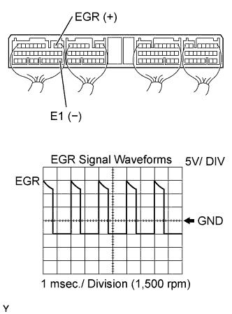
Connect the oscilloscope between terminals EGR and E1 of the ECM (E7) connector.
-
Turn the ignition switch ON.
-
Reference:
Inspection using the oscilloscope.
During EGR system is ON (engine speed 1,500 rpm), check the waveform between terminals EGR and E1 of ECM (E7) connector.
Tech Tips
The correct waveform is as shown.
NG
CHECK AND REPLACE ECM Click here
OK
-
-
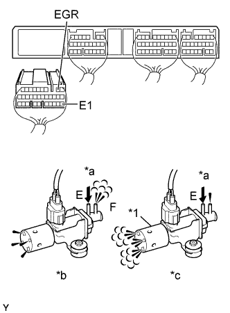
PERFORM ACTIVE TEST BY INTELLIGENT TESTER (CHECK ELECTRIC EGR CONTROL VALVE ASSEMBLY (E-VRV))
-
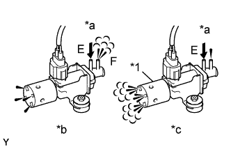
Text in Illustration *1 Air Filter *a Air *b E-VRV: ON *c E-VRV: OFF Disconnect the vacuum hoses from the E-VRV.
-
Connect the intelligent tester to the DLC3.
-
Turn the ignition switch ON and the push intelligent tester main switch ON.
-
Select the ACTIVE TEST mode on the intelligent tester.
-
Check the operation of the E-VRV when it is operated by the intelligent tester.
Result E-VRV is ON Air from port E flows out through port F. E-VRV is OFF Air from port E flows out through air filter.
OK
REPLACE ELECTRIC EGR CONTROL VALVE ASSEMBLY
NG
-
-
CHECK ELECTRIC EGR CONTROL VALVE ASSEMBLY (E-VRV)
-
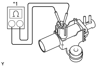
Text in Illustration *1 Ohmmeter Inspect the E-VRV for open circuit.
-
Using an ohmmeter, measure the resistance between terminals as shown.
Resistance 11 - 13 Ω at 20°C (68°F)
-
-
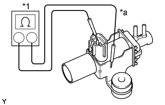
Text in Illustration *1 Ohmmeter *a No Continuity Inspect the E-VRV for ground.
-
Using an ohmmeter, check that there is no continuity between terminals and E-VRV body.
-
-
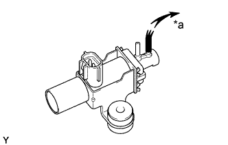
Text in Illustration *a Vacuum Inspect the E-VRV for air tightness.
-
Check that when vacuum is applied to the vacuum outlet port shown, the needle of vacuum pump indicates an increase of 66.7 kPa (500 mmHg, 19.7 in. Hg) or more.
-
-
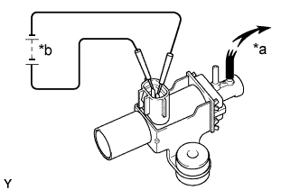
Text in Illustration *a 6 V *b Vacuum Inspect the E-VRV operation.
-
Apply about 6 V of DC power to the terminals.
-
Check that when vacuum is applied to the vacuum outlet port shown, the need does not move.
-
NG
REPLACE ELECTRIC EGR CONTROL VALVE ASSEMBLY
OK
-
-
CHECK WIRE HARNESS (ECM - E-VRV) (a) (E-VRV - EFI MAIN RELAY (MARKING: EFI)) (b)
-
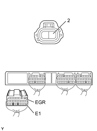
Check for open and short in harness and connector between ECM and E-VRV.
-
Disconnect the E-VRV connector.
-
Disconnect the ECM (E7) connector.
-
Check the continuity between the terminals E-VRV and ECM connector as shown in the illustration and table.
Continuity (Check for open) Terminal
(E-VRV ←→ ECM)
Standard 2 ←→ EGR (E7-2) Continuity Continuity (Check for short) Terminal
(ECM ←→ ECM(Ground))
Standard EGR (E7-2) ←→ E1 (E7-22) No continuity
-
-
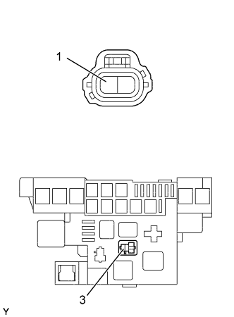
Check for open and short in harness and connector between the E-VRV and EFI main relay.
-
Remove the EFI main relay.
-
Disconnect the engine E-VRV connector.
-
Check the continuity between the terminals the E- VRV and EFI main relay of the R/B No. 2 (3) as shown in the illustration and table.
Standard (Check for open) Terminal
(EFI main relay of R/B No. 2 ←→ E-VRV)
Standard 3 ←→ 1 Continuity -
Check the continuity between the terminals of the E-VRV and body ground as shown in the illustration and table.
Standard (Check for short) Terminal
(E-VRV ←→ ECM(Ground))
Standard 1 ←→ Body ground No continuity
-
NG
REPAIR OR REPLACE HARNESS AND CONNECTOR
OK
-
-
CHECK ELECTRIC EGR CONTROL VALVE ASSEMBLY
NG
REPLACE ELECTRIC EGR CONTROL VALVE ASSEMBLY
OK 
CHECK AND REPLACE ECM Click here
-
REPAIR OR REPLACE VACUUM HOSE
NG
REPAIR OR REPLACE VACUUM HOSE
OK
-
CHECK VACUUM
-
Text in Illustration *1 Vacuum Gage Using a 3-way connector, connect a vacuum gauge to the hose between the VSV and EGR valve.
-
Warm up the engine to above 80°C (176°F).
-
Check the vacuum at 1,500 rpm.
Result Type Vacuum 1 0 kPa (0 mmHg, 0 in. Hg) 2 Above 28 kPa (210 mmHg, 8.3 in. Hg)
TYPE1
REPAIR OR REPLACE VACUUM HOSE
TYPE2
CHECK ELECTRIC EGR CONTROL VALVE ASSEMBLY (E-VRV) (CHECK FUNCTION) Click here
-
-
CHECK ELECTRIC EGR CONTROL VALVE ASSEMBLY (E-VRV) (CHECK FUNCTION)
-
Disconnect the ECM (E7) connector from the ECM.
-
Turn the ignition switch ON.
-
Check the E-VRV operation.
-
Connect between terminal EGR and E1 of the ECM (E7) connector (ON).
-
Disconnect between terminal EGR and E1 of the ECM (E7) connector (OFF).
E-VRV ON Air from port E flows out through port F. E-VRV OFF Air from port E flows out through air filter.
-
OK
CHECK AND REPLACE ECM Click here
NG
-
-
CHECK ELECTRIC EGR CONTROL VALVE ASSEMBLY (E-VRV)
-
Text in Illustration *1 Ohmmeter Inspect the E-VRV for open circuit.
-
Using an ohmmeter, measure the resistance between terminals as shown.
Resistance 11 - 13 Ω at 20°C (68°F)
-
-
Text in Illustration *1 Ohmmeter *a No Continuity Inspect the E-VRV for ground.
-
Using an ohmmeter, check that there is no continuity between terminals and E-VRV body.
-
-
Text in Illustration *a Vacuum Inspect the E-VRV for air tightness.
-
Check that when vacuum is applied to the vacuum outlet port shown, the needle of vacuum pump indicates an increase of 66.7 kPa (500 mmHg, 19.7 in. Hg) or more.
-
-
Text in Illustration *a Vacuum *b 6 V Inspect the E-VRV operation.
-
Apply about 6 V of DC power to the terminals.
-
Check that when vacuum is applied to the vacuum outlet port shown, the need does not move.
-
NG
REPLACE ELECTRIC EGR CONTROL VALVE ASSEMBLY
OK
-
-
CHECK WIRE HARNESS (ECM - E-VRV) (a) (E-VRV - EFI MAIN RELAY (MARKING EFI)) (b)
-
Check for open and short in harness and connector between ECM and E-VRV.
-
Disconnect the E-VRV connector.
-
Disconnect the ECM (E7) connector.
-
Check the continuity between the terminals of the E-VRV and ECM connector as shown in the illustration and table.
Continuity (Check for open) Terminal
(E-VRV ←→ ECM)
Standard 2 ←→ EGR (E7-2) Continuity Continuity (Check for short) Terminal
(ECM ←→ ECM(Ground))
Standard EGR (E7-2) ←→ E1 (E7-22) No continuity
-
-
Check for open and short in harness and connector between the E-VRV and EFI main relay.
-
Remove the EFI main relay.
-
Disconnect the engine E-VRV connector.
-
Check the continuity between the terminals of the E-VRV and EFI main relay of the R/B No. 2 (3) as shown in the illustration and table.
Standard (Check for open) Terminal
(EFI main relay of R/B No. 2 ←→ E-VRV)
Standard 3 ←→ 1 Continuity -
Check the continuity between the terminals of the E-VRV and body ground as shown in the illustration and table.
Standard (Check for short) Terminal
(E-VRV ←→ Ground)
Standard 1 ←→ Body ground No continuity
-
NG
REPAIR OR REPLACE HARNESS AND CONNECTOR
OK
-
-
CHECK ELECTRIC EGR CONTROL VALVE ASSEMBLY
NG
REPLACE ELECTRIC EGR CONTROL VALVE ASSEMBLY
OK
CHECK AND REPLACE ECM Click here