ECD SYSTEM Starter Signal Circuit
DESCRIPTION
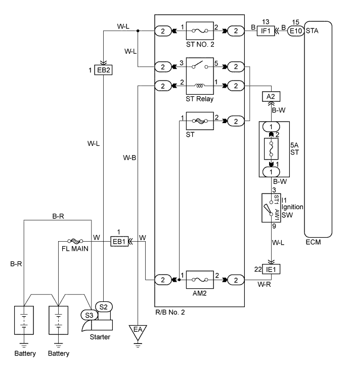
When the engine is being cranked, the intake air flow is slow, so fuel vaporization is poor. A rich mixture is therefore necessary in order to achieve good start ability. While the engine is being cranked, the battery positive voltage is applied to terminal STA of the ECM. The starter signal is mainly used to increase the fuel injection volume for the starting injection control and after-start injection control.
WIRING DIAGRAM
INSPECTION PROCEDURE
Tech Tips
-
This diagnostic chart is based on the premise that the engine is being cranked under normal conditions. If the engine does not crank, proceed to the problem symptoms table on page Click here.
-
When not using the intelligent tester go to step 4.
PROCEDURE
-
READ VALUE OF INTELLIGENT TESTER (CHECK STA SIGNAL)
-
Connect the intelligent tester to the DLC3.
-
Turn the ignition switch ON and push the intelligent tester main switch ON.
-
Read the STA signal on the intelligent tester while the starter operates.
Result Ignition Switch Position ON STA STA Signal OFF ON
OK 
PROCEED TO NEXT CIRCUIT INSPECTION SHOWN ON PROBLEM SYMPTOM TABLE Click here
NG 
-
-
CHECK FUSE (ST NO. 2)
-
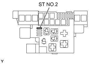
Remove the ST NO.2 fuse from the R/B No. 2.
-
Check continuity of ST NO. 2 fuse.
Result Continuity
NG
REPLACE FUSE
OK
-
-
CHECK WIRE HARNESS (ECM - STARTER RELAY)
-
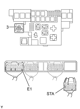
Disconnect the starter relay.
-
Disconnect the ECM (E10) connector.
-
Check the continuity between terminals of the starter relay (1) of the R/B No. 2 and ECM connector as shown in the illustration and table.
Continuity (Check for open) Terminal
(Starter relay of R/B No. 2 ←→ ECM)
Standard 3 ←→ STA (E10-15) Continuity Continuity (Check for short) Terminal
(ECM ←→ ECM(Ground))
Standard STA (E10-15) ←→ E1 (E7-22) No continuity
NG
REPAIR OR REPLACE HARNESS AND CONNECTOR
OK 
CHECK AND REPLACE ECM Click here
-
-
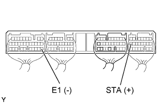
CHECK STARTER SIGNAL (CHECK VOLTAGE)
-
Turn the ignition switch START.
-
Check the voltage between terminals of the ECM connector as shown in the table and illustration.
Voltage Terminal
(Positive terminal ←→ Negative terminal)
Voltage STA (E10-15) ←→ E1 (E7-22) 6.0 V or more
OK
PROCEED TO NEXT CIRCUIT INSPECTION SHOWN ON PROBLEM SYMPTOM TABLE Click here
NG
-
-
CHECK FUSE (ST NO. 2)
-
Remove the ST NO.2 fuse from the R/B No. 2.
-
Check continuity of ST NO. 2 fuse.
Result Continuity
NG
REPLACE FUSE
OK
-
-
CHECK WIRE HARNESS (ECM - STARTER RELAY)
-
Disconnect the starter relay.
-
Disconnect the ECM (E10) connector.
-
Check the continuity between terminals of the starter relay (1) of the R/B No. 2 and ECM connector as shown in the illustration and table.
Continuity (Check for open) Terminal
(Starter relay of R/B No. 2 ←→ ECM)
Standard 3 ←→ STA (E10-15) Continuity Continuity (Check for short) Terminal
(ECM ←→ ECM(Ground))
Standard STA (E10-15) ←→ E1 (E7-22) No continuity
NG
REPAIR OR REPLACE HARNESS AND CONNECTOR
OK
CHECK AND REPLACE ECM Click here
-