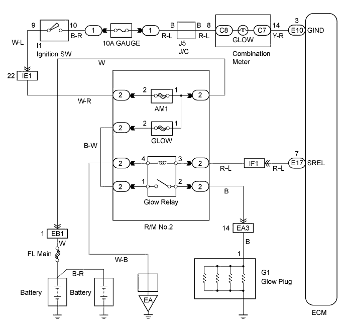
ECD SYSTEM Pre-heating Control Circuit
DESCRIPTION
-
DESCRIPTION
-
When the ignition switch turns ON, the ECM calculates the glow indicator lighting time/heating corresponding to the coolant temperature at that time and turns ON the glow indicator light/glow plug relay. As the ceramics is used for a glow plug material, the current control is not performed.
-
WIRING DIAGRAM
INSPECTION PROCEDURE
PROCEDURE
-
DOES GLOW INDICATOR LIGHT UP
-
Turn the ignition switch ON.
-
Does the glow indicator light up?
-
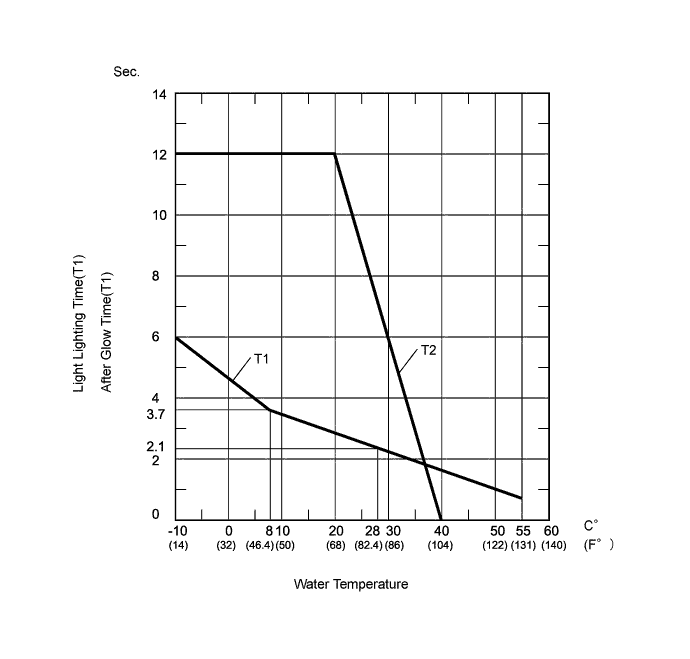
The glow indicator lights up for 0.5 sec. or more.
OK 
CHECK FOR INDICATOR LIGHTING TIME AND AFTER GLOW TIME Click here
NG 
-
-
CHECK ECM (CHECK VOLTAGE)
-
Disconnect the ECM (E10) connector.
-
Turn ignition switch ON.
-
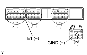
Check the voltage between terminals of the ECM connector s as shown in the table and illustration.
Voltage Terminal
(Positive terminal ←→ Negative terminal)
Voltage GIND (E10-3) ←→ E1 (E7-22) 9 - 14 V
OK 
CHECK AND REPLACE ECM Click here
NG
-
-
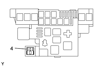
CHECK FUSE (GAUGE)
-
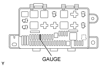
Remove the GAUGE fuse from the R/B No. 1.
-
Measure the continuity of the GAUGE fuse.
Result Continuity
NG
REPLACE FUSE
OK
-
-
CHECK GLOW INDICATOR LIGHT
OK
CHECK WIRE HARNESS
NG
REPLACE COMBINATION METER BULB NO. 1
-
CHECK FOR INDICATOR LIGHTING TIME AND AFTER GLOW TIME
NG
CHECK AND REPLACE ECM Click here
OK
-
ARE THERE ANY DTC BEING OUTPUT
YES
GO TO RELEVANT DTC CHART Click here
NO
-
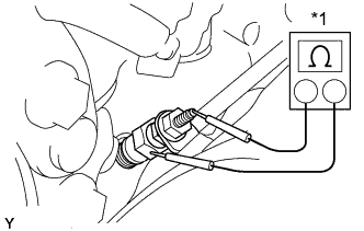
CHECK GLOW PLUG RELAY ASSEMBLY
-
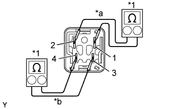
Text in Illustration *1 Ohmmeter *a No Continuity *b Continuity Remove the glow plug relay from the relay block No. 2.
-
Inspect the glow plug relay continuity.
-
Using an ohmmeter, check that there is no continuity between terminals 1 and 2.
-
Check that there is continuity between terminals 3 and 4.
-
-
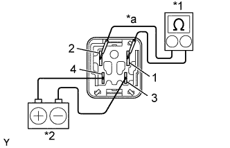
Text in Illustration *1 Ohmmeter *2 Battery *a Continuity Inspect the glow plug relay operation.
-
Apply battery voltage across terminals 3 and 4.
-
Using an ohmmeter, check that there is continuity between terminals 1 and 2.
-
NG
REPLACE GLOW PLUG RELAY ASSEMBLY
OK
-
-
CHECK ECM (CHECK VOLTAGE)
-
Disconnect the ECM (E10) connector.
-
Turn the ignition switch START.
-
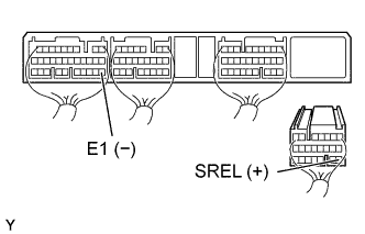
Check the voltage between terminals of shown in the table and illustration.
Voltage Terminal
(Positive terminal ←→ Negative terminal)
Voltage SREL (E10-16) ←→ E1 (E7-22) 0 - 0.3 V
NG
CHECK AND REPLACE ECM Click here
OK
-
-
CHECK WIRE HARNESS (ECM - GLOW PLUG RELAY) (a) (GLOW PLUG RELAY - BODY GROUND) (b)
-
Check for open and short in harness and connector between ECM and glow plug relay.
-
Remove the glow plug relay.
-
Disconnect the ECM (E10) connector.
-
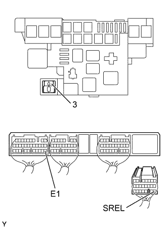
Check the continuity between terminals of the glow plug relay (3) of R/B No. 2 and ECM connector as shown in the illustration and table.
Standard (Check for open) Terminal
(Glow plug relay of R/B No. 2 ←→ ECM)
Standard 3 ←→ SREL (E10-16) Continuity Standard (Check for short) Terminal
(ECM ←→ ECM(Ground))
Standard SREL (E10-16) ←→ E1 (E7-22) No continuity
-
-
Check for open and short in harness and connector between the glow plug relay and body ground.
-
Remove the glow plug relay.
-
Check the continuity between terminals of the glow plug relay (4) of the R/B No. 2 and body ground as shown in the illustration and table.
Standard (Check for open) Terminal
(Glow plug relay of R/B No. 2 ←→ Body ground)
Standard 4 ←→ Body ground Continuity
-
NG
REPAIR HARNESS AND CONNECTOR
OK
-
-
CHECK GLOW PLUG ASSEMBLY (CHECK RESISTANCE)
-
Text in Illustration *1 Ohmmeter Using an ohmmeter, check that there is continuity between the glow plug terminal and ground.
Standard resistance Approx. 0.72 Ω at 20°C (68°F)
NG
REPLACE GLOW PLUG RELAY ASSEMBLY
OK
-
-
CHECK GLOW PLUG ASSEMBLY (CHECK INSTALLATION)
NG
TIGHTEN GLOW PLUG
OK
-
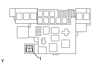
CHECK WIRE HARNESS (GLOW PLUG - GLOW PLUG RELAY) (a) (GLOW PLUG RELAY - BATTERY) (b)
-
Check for open and short in harness and connector between the glow plug and glow plug relay.
-
Remove the glow plug relay.
-
Disconnect the glow plug wire.
-
Check the continuity between terminals of the glow plug relay (2) of the R/B No. 2 and glow plug wire as shown in the illustration and table.
Standard (Check for open) Terminal
(Glow plug relay of R/B No. 2 ←→ Glow plug wire)
Standard 2 ←→ Glow plug wire Continuity Standard (Check for short) Terminal
(Glow plug wire ←→ Body ground)
Standard Glow plug wire ←→ Body ground No continuity
-
-
Check for open and short in harness and connector between the glow plug relay and battery positive terminal wire.
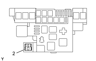
-
Remove the GLOW fuse from the R/B No. 2.
-
Check the continuity of the GLOW fuse.
Result Continuity -
Reinstall the GLOW fuse.
-
Remove the glow plug relay.
-
Disconnect the battery positive terminal.
-
Check continuity between the terminals of the glow plug relay (1) of the R/B No. 2 and battery positive terminal wire.
Standard (Check for open) Terminal
(Glow plug relay of R/B No. 2 ←→ Battery)
Standard 1 ←→ Battery positive terminal Continuity
-
NG
REPAIR HARNESS AND CONNECTOR
OK 
PROCEED TO NEXT CIRCUIT INSPECTION SHOWN ON PROBLEM SYMPTOM TABLE Click here
-