ECD SYSTEM, Diagnostic DTC:97
| DTC Code | DTC Name |
|---|---|
| 97 | EDU Circuit Malfunction |
DESCRIPTION
The ECU has been adopted to drive the injector at high speeds. The EDU has realized high-speed driving under high fuel pressure conditions through the use of a DC/DC converter that provides a high-voltage, quick-charging system.
The ECM constantly monitors the EDU and stops the engine in case an abnormal condition is detected.
| DTC No. | DTC Detecting Condition | Trouble Area |
| 97 | Open or short in EDU circuit |
|
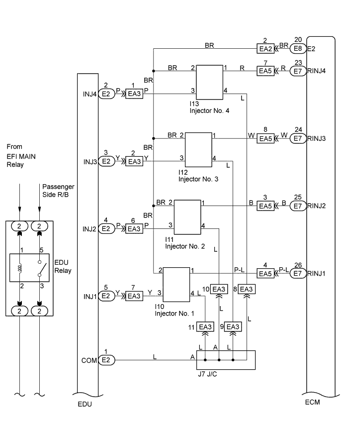
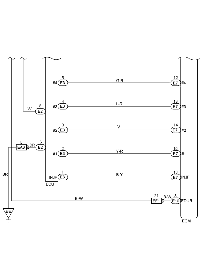
WIRING DIAGRAM
INSPECTION PROCEDURE
Tech Tips
Read freeze frame data using intelligent tester. Because freeze frame records the engine conditions when the malfunction is detected. When troubleshooting, it is useful for determining whether the vehicle was running or stopped, the engine was warmed up or not, the air-fuel ration was lean or rich, etc. at the time of the malfunction.
PROCEDURE
-
CHECK SPILL VALVE CONTROL DRIVER ASSEMBLY (CHECK VOLTAGE POWER SOURCE)
-
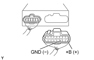
Disconnect the EDU (E2) connector.
-
Turn the ignition switch ON.
-
Check the voltage between terminals of the EDU connector as shown in the table and illustration.
Voltage Terminal
(Positive terminal ←→ Negative terminal)
Voltage +B (E2-8) ←→ GND (E2-6) 9 - 14 V
NG 
CHECK EDU POWER SOURCE CIRCUIT Click here
OK 
-
-
CHECK SPILL VALVE CONTROL DRIVER ASSEMBLY (CHECK RESISTANCE)
-
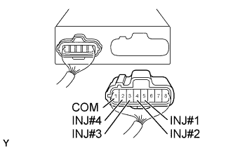
Disconnect the EDU (E2) connector.
-
Check the resistance between terminals of the EDU connector as shown in the table and illustration.
Resistance (at 20°C (68°F)) Terminal Resistance COM (E2-1) ←→ 2 2.5 - 3.1 Ω INJ#1 (E2-5) ←→ 2 INJ#2 (E2-4) ←→ 2 INJ#3 (E2-3) ←→ 2 INJ#4 (E2-2) ←→ 2
OK 
CHECK INJECTION PUMP ASSEMBLY (SUCTION CONTROL VALVE) Click here
NG
-
-
CHECK INJECTOR ASSEMBLY
-
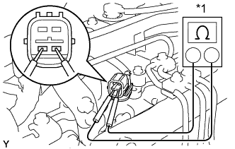
Text in Illustration *1 Ohmmeter Disconnect the 4 injector connectors.
-
Using an ohmmeter, measure the resistance between terminals as shown.
Resistance 2.5 - 3.1 Ω at 20°C (68°F) -
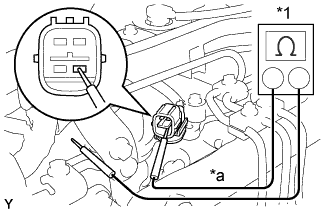
Text in Illustration *1 Ohmmeter *a No Continuity Using an ohmmeter, check that there is no continuity between the injector terminal and ground as shown.
OK
REPAIR OR REPLACE HARNESS AND CONNECTOR
NG
REPLACE INJECTOR ASSEMBLY
-
-
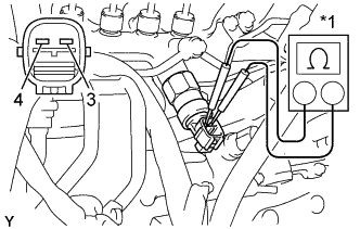
CHECK INJECTION PUMP ASSEMBLY (SUCTION CONTROL VALVE)
-
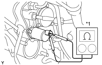
Text in Illustration *1 Ohmmeter Disconnect the suction control valve connector.
-
Using an ohmmeter, measure the resistance between terminals as shown.
Resistance 1.95 - 2.27 Ω at 20°C (68°F) -
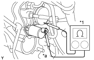
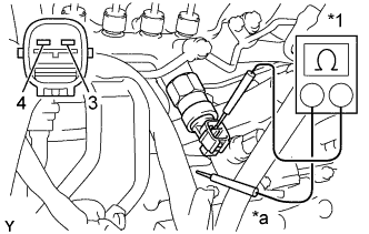
Text in Illustration *1 Ohmmeter *a No Continuity Using an ohmmeter, check that there is no continuity between the terminal and ground as shown.
NG
REPLACE SUCTION CONTROL VALVE (See FUEL - SUCTION CONTROL VALVE - REPLACEMENT)
OK
-
-
CHECK COMMON RAIL ASSEMBLY (FUEL RELIEF VALVE)
-
Text in Illustration *1 Ohmmeter Disconnect the fuel relief valve connector.
-
Using an ohmmeter, measure the resistance between terminals as shown.
Resistance 2.6 - 2.8 Ω at 20°C (68°F) -
Text in Illustration *1 Ohmmeter *a No Continuity Using an ohmmeter, check that there is no continuity between the terminal and ground as shown.
NG
REPLACE COMMON RAIL ASSEMBLY Click here
OK
-
-
CHECK WIRE HARNESS (ECM - SCV) (a) (ECM - FUEL RELIEF VALVE) (b)
-
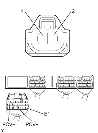
Check for open and short in harness and connector between ECM and SCV.
-
Disconnect the SCV connector.
-
Disconnect the ECM (E7) connector.
-
Check the continuity between terminals of the SCV and ECM connectors as shown in the illustration and table.
Continuity (Check for open) Terminal
(SCV ←→ ECM)
Standard 2 ←→ PCV- (E7-9) Continuity 1 ←→ PCV+ (E7-8) Continuity (Check for short) Terminal
(ECM ←→ ECM(Ground))
Standard PCV- (E7-9) ←→ E1 (E7-22) No continuity PCV+ (E7-8) ←→ E1 (E7-22)
-
-
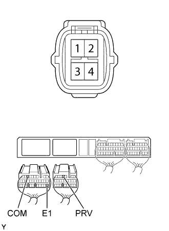
Check for open and short in harness and connector between the ECM and fuel relief valve.
-
Disconnect the fuel relief valve connector.
-
Disconnect the ECM (E8) and (E7) connectors.
-
Check the continuity between terminals of fuel relief valve and ECM connectors as shown in the illustration and table.
Continuity (Check for open) Terminal
(Fuel relief valve ←→ ECM)
Standard 3 ←→ PRV (E8-4) Continuity 4 ←→ COM (E7-7) Continuity (Check for short) Terminal
(ECM ←→ ECM(Ground))
Standard PRV (E8-4) ←→ E1 (E7-22) No continuity COM (E7-7) ←→ E1 (E7-22)
-
NG
REPAIR OR REPLACE HARNESS AND CONNECTOR
OK
-
-
CHECK ECM (CHECK VOLTAGE)
-
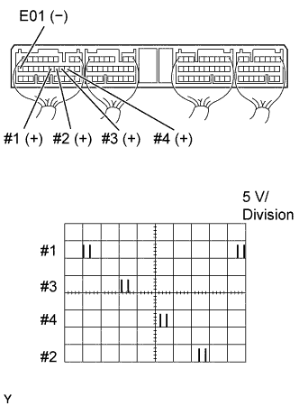
During cranking or idling, check the waveform between terminals #1, #2, #3, #4 and E01 of the ECM (E7) connector with the oscilloscope.
Voltage The correct waveform are as shown.
NG
CHECK AND REPLACE ECM Click here
OK
-
-
CHECK ECM (CHECK VOLTAGE)
-
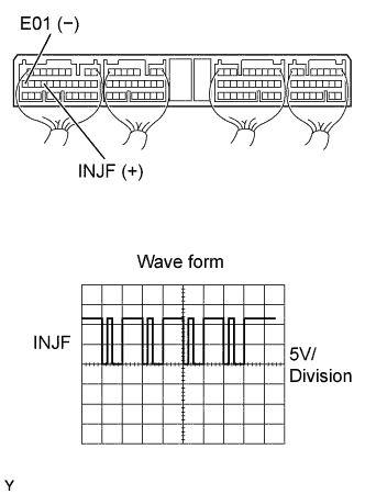
During cranking or idling, check the wave form between terminals INJF and E01 of the ECM (E7) connector with the oscilloscope.
Voltage The correct waveform are as shown.
NG
CHECK AND REPLACE ECM Click here
NG
-
-
CHECK WIRE HARNESS (ECM - EDU)
-
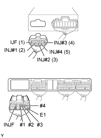
Disconnect the EDU (E3) connector.
-
Disconnect the ECM (E7) connector.
-
Check the continuity between terminals of the EDU and ECM connectors as shown in the illustration and table.
Continuity (Check for open) Terminal
(EDU ←→ ECM)
Standard IJF (E3-1) ←→ INJF (E7-18) Continuity IJT#1 (E3-2) ←→ #1 (E7-15) IJT#2 (E3-3) ←→ #2 (E7-14) IJT#3 (E3-4) ←→ #3 (E7-13) IJT#4 (E3-5) ←→ #4 (E7-12) Continuity (Check for short) Terminal
(ECM ←→ ECM(Ground))
Standard INJF (E7-18) ←→ E1 (E7-22) No continuity #1 (E7-15) ←→ E1 (E7-22) #2 (E7-14) ←→ E1 (E7-22) #3 (E7-13) ←→ E1 (E7-22) #4 (E7-12) ←→ E1 (E7-22)
OK
REPAIR OR REPLACE HARNESS AND CONNECTOR
OK 
REPLACE SPILL VALVE CONTROL DRIVER ASSEMBLY Click here
-