ECD SYSTEM, Diagnostic DTC:96
| DTC Code | DTC Name |
|---|---|
| 96 | EGR Valve Position Sensor Circuit Malfunction |
DESCRIPTION
| DTC No. | DTC Detecting Condition | Trouble Area |
| 96 | To EGLS signal to ECM for 1.0 sec. or more |
|
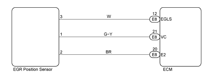
WIRING DIAGRAM
INSPECTION PROCEDURE
Tech Tips
Read freeze frame data using intelligent tester. Because freeze frame records the engine conditions when the malfunction is detected, when troubleshooting it is useful for determining whether the vehicle was running or stopped, the engine warmed up or not, the air-fuel ratio lean or rich, etc. at the time of the malfunction.
PROCEDURE
-
CHECK ELECTRIC EGR CONTROL VALVE ASSEMBLY
-
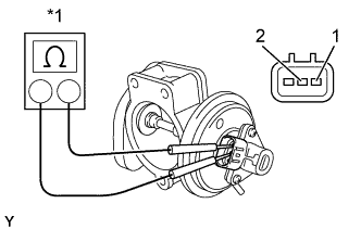
Text in Illustration *1 Ohmmeter Using an ohmmeter, check the resistance between terminals 1 and 2 of the EGR lift sensor.
Resistance 2.6 kΩ at 20°C (68°F) -
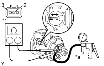
Text in Illustration *1 Ohmmeter *a Vacuum Apply vacuum to the diaphragm chamber and then check each resistance between terminals 3 and 2 of the lift sensor when the valve is fully opened and also when fully closed.
Resistance EGR Valve Resistance Fully opened 0.6 kΩat 20°C (68°F) Fully closed 2.2 kΩat 20°C (68°F) Tech Tips
The resistance value increases in proportion to the opening angle of the EGR valve.
NG 
REPLACE ELECTRIC EGR CONTROL VALVE ASSEMBLY
OK 
-
-
CHECK ECM (CHECK VOLTAGE)
-
Turn the ignition switch ON.
-
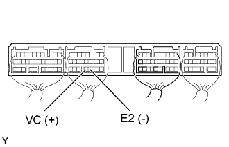
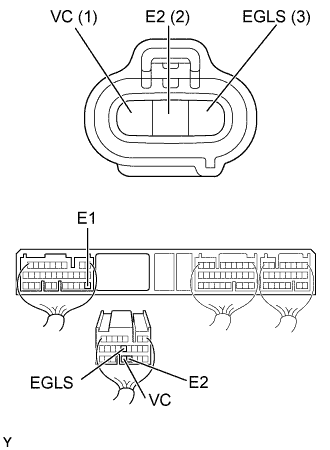
Check the voltage between terminals shown in the table and illustration.
Voltage Terminal
(Positive terminal ←→ Negative terminal)
Voltage VC (E8-21) ←→ E2 (E8-20) 4.5 - 5.5 V
NG
CHECK AND REPLACE ECM Click here
OK
-
-
CHECK WIRE HARNESS (ECM - EGR POSITION SENSOR)
-
Disconnect the turbo pressure sensor connector.
-
Disconnect the ECM (E8) connector.
-
Check the continuity between terminals of the EGR position sensor and ECM connectors as shown in the illustration and table.
Continuity (Check for open) Terminal
(EGR position sensor ←→ ECM)
Standard EGLS (3) ←→ EGLS (E8-12) Continuity VC (1) ←→ VC (E8-21) E2 (2) ←→ E2 (E8-20) Continuity (Check for short) Terminal
(ECM ←→ ECM(Ground))
Standard EGLS (E8-12) ←→ E1 (E7-22) No continuity VC (E8-21) ←→ E1 (E7-22)
NG
REPAIR OR REPLACE HARNESS AND CONNECTOR
OK
-
-
INSPECT SENSOR INSTALLATION
NG
TIGHTEN SENSOR
OK 
CHECK AND REPLACE ECM Click here