ECD SYSTEM, Diagnostic DTC:78(2), 78(3)
| DTC Code | DTC Name |
|---|---|
| 78(2) | Fuel Pump Circuit Malfunction (Open Circuit) |
| 78(3) | Fuel Pump Circuit Malfunction (Over Force Feed) |
DESCRIPTION
Supply pump is a single type and has a circuits of the fuel suction and force feed processes that achieve both high pressure force feed of fuel and reduction of driving torque.
In the suction process, it control SCV (Suction Control Valve) which suctions fuel by a plunger.
| DTC No. | DTC Detecting Condition | Trouble Area |
| 78 (2) 78 (3) |
Pressure change of common rail against supply quantity of supply pump is abnormal |
|
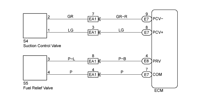
WIRING DIAGRAM
INSPECTION PROCEDURE
Tech Tips
-
Read freeze frame data using intelligent tester. Because freeze frame records the engine conditions when the malfunction is detected. When troubleshooting, it is useful for determining whether the vehicle was running or stopped, the engine was warmed up or not, the air-fuel ratio was lean or rich, etc. at the time of the malfunction.
-
When not using the intelligent tester go to step 6.
PROCEDURE
-
ARE THERE ANY OTHER CODES BEING OUTPUT? (BESIDES DTC 39, DTC 49, OR DTC 97)
YES 
GO TO RELEVANT DTC CHART Click here
NO 
-
CHECK INJECTION PUMP ASSEMBLY (SUCTION CONTROL VALVE)
-
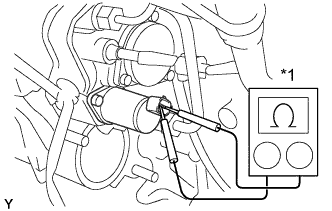
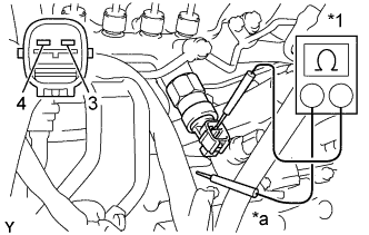
Text in Illustration *1 Ohmmeter Disconnect the suction control valve connector.
-
Using an ohmmeter, measure the resistance between terminals as shown.
Resistance 1.95 - 2.25 Ω at 20°C (68°F) -
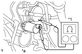
Text in Illustration *1 Ohmmeter *a No Continuity Using an ohmmeter, check that there is no continuity between the terminal and ground as shown.
NG
REPLACE SUCTION CONTROL VALVE (See FUEL - SUCTION CONTROL VALVE - REPLACEMENT)
OK
-
-
CHECK COMMON RAIL ASSEMBLY (FUEL RELIEF VALVE)
-
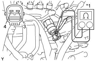
Text in Illustration *1 Ohmmeter Disconnect the fuel relief valve connector.
-
Using an ohmmeter, measure the resistance between terminals as shown.
Resistance 2.6 - 2.8 Ω at 20°C (68°F) -
Text in Illustration *1 Ohmmeter *a No Continuity Using an ohmmeter, check that there is no continuity between the terminal and ground as shown.
NG
REPLACE COMMON RAIL ASSEMBLY Click here
OK
-
-
CHECK WIRE HARNESS (ECM - SCV) (a) (ECM - FUEL RELIEF VALVE) (b)
-
Check for open and short in harness and connector between ECM and SCV.
-
Disconnect the SCV connector.
-
Disconnect the ECM (E7) connector.
-
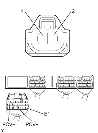
Check the continuity between terminals of the SCV and ECM connectors as shown in the illustration and table.
Continuity (Check for open) Terminal
(SCV ←→ ECM)
Standard 2 ←→ PCV- (E7-9) Continuity 1 ←→ PCV+ (E7-8) Continuity (Check for short) Terminal
(ECM ←→ ECM(Ground))
Standard PCV- (E7-9) ←→ E1 (E7-22) No continuity PCV+ (E7-8) ←→ E1 (E7-22)
-
-
Check for open and short in harness and connector between ECM and fuel relief valve.
-
Disconnect the fuel relief valve connector.
-
Disconnect the ECM (E8) and (E7) connectors.
-
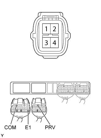
Check the continuity between terminals of the fuel relief valve and ECM connectors as shown in the illustration and table.
Continuity (Check for open) Terminal
(Fuel relief valve ←→ ECM)
Standard 3 ←→ PRV (E8-4) Continuity 4 ←→ COM (E7-7) Continuity (Check for short) Terminal
(ECM ←→ ECM(Ground))
Standard PRV (E8-4) ←→ E1 (E7-22) No continuity COM (E7-7 ←→ E1 (E7-22)
-
NG
REPAIR OR REPLACE HARNESS AND CONNECTOR
OK
-
-
CHECK ECM (CHECK VOLTAGE)
-
Reference:
Inspection using the oscilloscope.
-
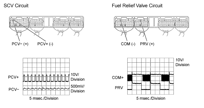
Check the SCV circuit.
During cranking or idling, check the waveforms between terminals PCV- and PCV+ of the ECM (E7) connector.
-
Check the fuel relief valve circuit.
During engine speed decreasing after racing, check the waveforms between terminals PRV of the ECM (E8) connector and COM of the ECM (E7) connector.
Tech Tips
The correct waveforms are as shown.
NG
CHECK AND REPLACE ECM Click here
OK 
REPLACE SUCTION CONTROL VALVE (See FUEL - SUCTION CONTROL VALVE - REPLACEMENT)
-
-
CHECK INJECTION PUMP ASSEMBLY (SUCTION CONTROL VALVE)
-
Text in Illustration *1 Ohmmeter Disconnect the suction control valve connector.
-
Using an ohmmeter, measure the resistance between terminals as shown.
Resistance 1.95 - 2.25 Ω at 20°C (68°F) -
Text in Illustration *1 Ohmmeter *a No Continuity Using an ohmmeter, check that there is no continuity between the terminal and ground as shown.
NG
REPLACE SUCTION CONTROL VALVE (See FUEL - SUCTION CONTROL VALVE - REPLACEMENT)
OK
-
-
CHECK COMMON RAIL ASSEMBLY (FUEL RELIEF VALVE)
-
Text in Illustration *1 Ohmmeter Disconnect the fuel relief valve connector.
-
Using an ohmmeter, measure the resistance between terminals as shown.
Resistance 2.6 - 2.8 Ω at 20°C (68°F) -
Text in Illustration *1 Ohmmeter *a No Continuity Using an ohmmeter, check that there is no continuity between the terminal and ground as shown.
NG
REPLACE COMMON RAIL ASSEMBLY Click here
OK
-
-
CHECK WIRE HARNESS (ECM - SCV) (a) (ECM - (FUEL RELIEF VALVE) (b)
-
Check for open and short in harness and connector between ECM and SCV.
-
Disconnect the SCV1 connector.
-
Disconnect the ECM (E7) connector.
-
Check the continuity between terminals of the SCV and ECM connectors as shown in the illustration and table.
Continuity (Check for open) Terminal
(SCV ←→ ECM)
Standard 2 ←→ PCV- (E7-9) Continuity 1 ←→ PCV+ (E7-8) Continuity (Check for short) Terminal
(ECM ←→ ECM(Ground))
Standard PCV- (E7-9) ←→ E1 (E7-22) No continuity PCV+ (E7-8) ←→ E1 (E7-22)
-
-
Check for open and short in harness and connector between the ECM and SCV2.
-
Disconnect the fuel relief valve connector.
-
Disconnect the ECM (E8) and (E7) connectors.
-
Check the continuity between terminals of fuel relief valve and ECM connectors as shown in the illustration and table.
Continuity (Check for open) Terminal
(Fuel relief valve ←→ ECM)
Standard 3 ←→ PRV (E8-4) Continuity 4 ←→ COM (E7-7) Continuity (Check for short) Terminal
(ECM ←→ ECM(Ground))
Standard PRV (E8-4) ←→ E1 (E7-22) No continuity COM (E7-7 ←→ E1 (E7-22)
-
NG
REPAIR OR REPLACE HARNESS AND CONNECTOR
OK
-
-
CHECK ECM (CHECK VOLTAGE)
-
Reference:
Inspection using the oscilloscope.
-
Check the SCV circuit.
During cranking or idling, check the waveforms between terminals PCV- and PCV+ of the ECM (E7) connector.
-
Check the fuel relief valve circuit.
During engine speed decreasing after racing, check the waveforms between terminals PRV of the ECM (E8) connector and COM of the ECM (E7) connector.
Tech Tips
The correct waveforms are as shown.
NG
CHECK AND REPLACE ECM Click here
OK
-
-
CHECK ENGINE START
NO
REPLACE INJECTOR ASSEMBLY Click here
NO
REPLACE COMMON RAIL ASSEMBLY Click here
YES
REPLACE SUCTION CONTROL VALVE (See FUEL - SUCTION CONTROL VALVE - REPLACEMENT)