ECD SYSTEM, Diagnostic DTC:51
| DTC Code | DTC Name |
|---|---|
| 51 | Stop Light Switch Circuit Malfunction |
DESCRIPTION
In this system, the signal of the stoplight switch is used for the judgement to detect abnormality in the acceleration system.
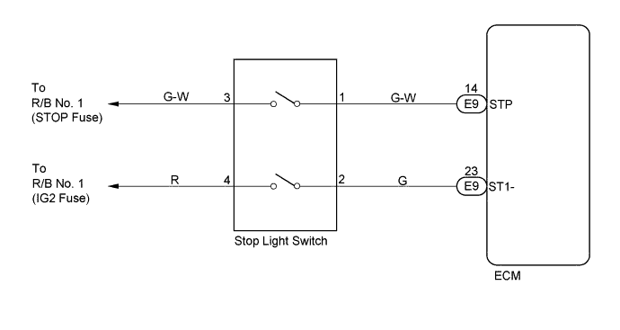
The stoplight switch has a duplex system (STP and ST1-) .
That is to memorize the abnormality when the signals at the time of depressing and nondepressing the brake pedal are detected simultaneously.
| DTC No. | DTC Detecting Condition | Trouble Area |
| 51 | When STP (without depressing the brake pedal) and ST1- (with the brake pedal depressed) signals continue for longer than 0.5 seconds with the ignition switch ON |
|
WIRING DIAGRAM
INSPECTION PROCEDURE
Tech Tips
Read freeze frame data using the intelligent tester, as freeze frame data records the engine conditions when the malfunction is detected. When troubleshooting, it is useful for determining whether the vehicle was running or stopped, the engine was warmed up or not, the air-fuel ratio was lean or rich, etc. at the time of the malfunction.
PROCEDURE
-
CHECK OPERATION OF STOP LIGHT
-
Check if the stop lights go on and off normally when the brake pedal is depressed and released.
NG 
REPAIR STOP LIGHT SWITCH CIRCUIT
OK 
-
-
INSPECT ECM (CHECK VOLTAGE)
-
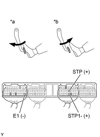
Text in Illustration *a Brake Pedal Depressed *b Brake Pedal Released Turn the ignition switch ON.
-
Check the voltage between terminal of ECM connector as shown in the table and illustration.
Voltage Brake Pedal Terminal
(Positive terminal ←→ Negative terminal)
Voltage Depressed STP (E9-14) ←→ E1 (E7-22) 7.5 - 1.4 V ST1- (E9-14) ←→ E1 (E7-22) Below 1.5 V Released STP (E9-14) ←→ E1 (E7-22) Below 1.5 V ST1- (E9-14) ←→ E1 (E7-22) 7.5 - 14 V
OK
CHECK INTERMITTENT PROBLEMS Click here
NG
-
-
CHECK WIRE HARNESS (ECM - STOP LIGHT SWITCH)
-
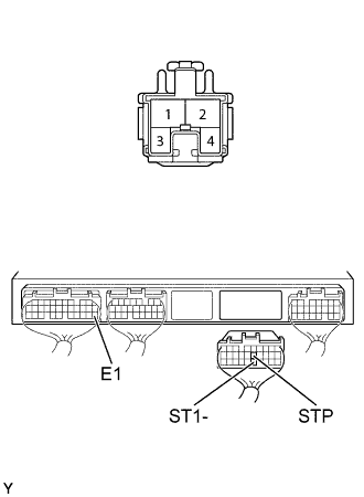
Disconnect the stop light switch connector.
-
Disconnect the ECM (E9) connector.
-
Check the continuity between terminals of the stop light switch and ECM connectors as shown in the illustration and table.
Continuity (Check for open) Terminal
(Stop light switch ←→ ECM)
Standard 1 ←→ STP (E9-14) Continuity 3 ←→ ST1- (E9-23) Continuity (Check for short) Terminal
(ECM ←→ ECM(Ground))
Standard STP (E9-14) ←→ E1 (E7-22) No continuity ST1- (E9-23) ←→ E1 (E7-22)
NG
REPAIR OR REPLACE HARNESS AND CONNECTOR
OK 
CHECK AND REPLACE ECM Click here
-