ECD SYSTEM, Diagnostic DTC:39
| DTC Code | DTC Name |
|---|---|
| 39 | Fuel Temperature Sensor Circuit Malfunction |
DESCRIPTION
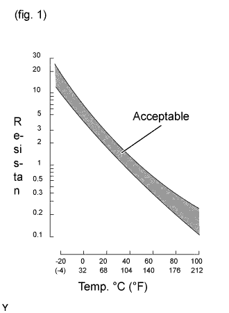
The fuel temperature sensor senses the fuel temperature. A thermistor built into the sensor changes the resistance value according to the fuel temperature. The lower the fuel temperature, the greater the thermistor resistance value, and the higher the fuel temperature, the lower the thermistor resistance value (See Fig. 1).
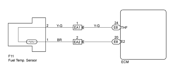
The fuel temperature sensor is connected to the ECU (See below). The 5 V power source voltage in the ECU is applied to the fuel temperature sensor from terminal THF via a resistor R. That is, resistor R and the fuel temperature sensor are connected in series. When the resistance value of the fuel temperature sensor changes in accordance with changes in the fuel temperature, the potential at terminal THF also changes. Based on this signal, the ECU. Based on this signal, the ECU performs the pressure control compensation of the supply pump and error detection compensation of the highly pressurized fuel system.
| DTC No. | DTC Detecting Condition | Trouble Area |
| 39 | Open or short in fuel temp. sensor circuit for 0.5 sec. or more |
|
Tech Tips
After confirming DTC No. 39, use the intelligent tester to confirm the fuel temperature from the CURRENT DATA.
| Temperature displayed | Malfunction |
| -40°C (-40°F) | Open circuit |
| 140°C (284°F) or more | Short circuit |
WIRING DIAGRAM
INSPECTION PROCEDURE
Tech Tips
-
If DTC Nos. 22, 24, 35 and 39 are output simultaneously, E2 (sensor ground) may be open.
-
Read freeze frame data using intelligent tester. Because freeze frame records the engine conditions when the malfunction is detected. When troubleshooting it is useful for determining whether the vehicle was running or stopped, the engine was warmed up or not, the air-fuel ratio was lean or rich, etc. at the time of the malfunction.
-
When not using the intelligent tester go to step 6.
PROCEDURE
-
READ VALUE OF INTELLIGENT TESTER (FUEL TEMP.)
-
Connect the intelligent tester to the DLC3.
-
Turn the ignition switch ON and push the intelligent tester main switch ON.
-
Read the temperature value on the intelligent tester.
Temp Same as actual fuel temperature. Result A B OK -40°C (-40°F) 140°C (248°F) or more Same as actual fuel temperature Tech Tips
-
If there is open circuit, intelligent tester indicates -40°C (-40°F) (A).
-
If there is short circuit, intelligent tester indicates 140°C (284°F) or more (B).
-
OK 
CHECK FOR INTERMITTENT PROBLEMS Click here
A 
CHECK ECM (CHECK FOR OPEN) Click here
B
CHECK ECM (CHECK FOR SHORT) Click here
-
-
CHECK ECM (CHECK FOR OPEN)
-
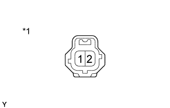
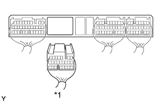
Text in Illustration *1 Fuel Temp. Sensor Disconnect the fuel temperature sensor connector.
-
Connect the sensor wire harness terminals together.
-
Turn the ignition switch ON.
-
Read the temperature value on the intelligent tester.
Temperature value 140°C (284°F) or more -
Confirm good connection at sensor.
OK
REPLACE INJECTION PUMP ASSEMBLY
NG 
-
-
CHECK ECM (CHECK FOR OPEN)
-
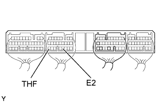
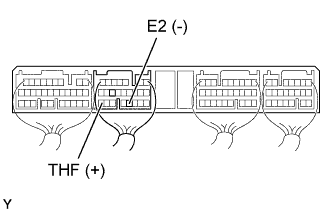
Connect between terminals THF and E2 of the ECU E8 connector.
Tech Tips
The fuel temperature sensor connector is disconnected. Before checking, do a visual and contact pressure check for the ECU connector Click here.
-
Turn the ignition switch ON.
-
Read the temperature value on the intelligent tester.
Temperature value 140°C (284°F) or more -
Confirm good connection at sensor.
NG
REPLACE ECM
OK
REPAIR OR REPLACE HARNESS AND CONNECTOR
-
-
CHECK ECM (CHECK FOR SHORT)
-
Disconnect the fuel temperature sensor connector.
-
Turn the ignition switch ON.
-
Read the temperature value on the intelligent tester.
Temperature value -40°C (-40°F)
OK
REPLACE FUEL TEMPERATURE SENSOR
NG
-
-
CHECK ECM (CHECK FOR SHORT)
-
Text in Illustration *1 E8 Connector Disconnect the ECU (E8) connector.
Tech Tips
The fuel temperature sensor connector is disconnected.
-
Read the temperature value on the intelligent tester.
Temperature value -40°C (-40°F)
OK
REPAIR OR REPLACE HARNESS AND CONNECTOR
NG 
CHECK AND REPLACE ECM Click here
-
-
CHECK ECM (CHECK VOLTAGE)
-
Turn the ignition switch ON.
-
Check the voltage between terminals of the ECM connector as shown in the table and illustration.
Voltage Fuel Temp.
°C (°F)
Terminal
(Positive terminal ←→ Negative terminal)
Voltage 20 (68)
(Engine is cool)
THF (E8-24) ←→ E2 (E8-20) 0.2 - 3.8 V 80 (176)
(Engine is hot)
THF (E8-24) ←→ E2 (E8-20) 0.1 - 1.5 V
OK
CHECK FOR INTERMITTENT PROBLEMS Click here
NG
-
-
INSPECT FUEL TEMPERATURE SENSOR (CHECK RESISTANCE)
-
Disconnect the fuel temp. sensor connector.
-
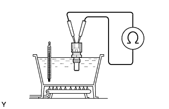
Remove fuel temperature sensor.
-
Measure resistance between terminals.
Resistance Within acceptable zone on the chart below Water temp.
°C (°F)
Resistance 20 (68) 2 - 3 kΩ 80 (176) 0.2 - 0.4 kΩ
NG
REPLACE FUEL TEMPERATURE SENSOR
OK
-
-
CHECK WIRE HARNESS (ECM - FUEL TEMPERATURE SENSOR)
-
Disconnect the fuel temp. sensor connector.
-
Disconnect the ECU (E8) connector.
-
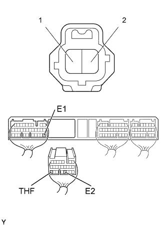
Check the continuity between terminals of the fuel temp. sensor and ECM connectors as shown in the illustration and table.
Continuity (Check for open) Terminal
(Fuel temp. sensor ←→ ECM)
Standard 2 ←→ THF (E8-24) Continuity 1 ←→ E2 (E8-20) Continuity (Check for short) Terminal
(ECM ←→ ECM(Ground))
Standard THF (E8-24) ←→ E1 (E7-22) No continuity
NG
REPAIR OR REPLACE HARNESS AND CONNECTOR
OK
CHECK AND REPLACE ECM Click here
-