ECD SYSTEM, Diagnostic DTC:42
| DTC Code | DTC Name |
|---|---|
| 42 | Vehicle Speed Sensor Signal Circuit Malfunction |
DESCRIPTION
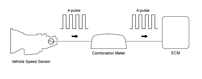
The vehicle speed sensor outputs a 4-pulse signal for every revolution of the rotor shaft, which is rotated by the transmission output shaft via the driven gear. After this signal is converted into a more precise rectangular waveform by the waveform shaping circuit inside the combination meter, it is then transmitted to the ECM. The ECM determines the vehicle speed based on the frequency of these pulse signals.
| DTC No. | DTC Detecting Condition | Trouble Area |
| 42 | All conditions below are detected continuously for 8 sec. or more: (a) Vehicle speed signal: 0 km/h (0 mph) (b) Engine speed: 2,400 - 4,000 rpm (c) Engine coolant temp.: 60°C (176°F) or more (d) Accelerator pedal opening angle : 29 % or more |
|
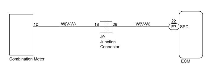
WIRING DIAGRAM
INSPECTION PROCEDURE
Tech Tips
Read freeze frame data using intelligent tester. Because freeze frame records the engine conditions when the malfunction is detected. When troubleshooting it is useful for determining whether the vehicle was running or stopped, the engine was warmed up or not, the air-fuel ratio was lean or rich, etc. at the time of the malfunction.
PROCEDURE
-
CHECK OPERATION OF SPEED METER
Drive the vehicle and check if the operation of the speedometer in the combination meter is normal.
Tech Tips
The vehicle speed sensor is operating normally if the speedometer display is normal.
NG 
GO TO COMBINATION METER SYSTEM Click here
OK 
-
CHECK ECM (CHECK VOLTAGE)
-
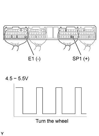
Shift the shift lever to the neutral.
-
Jack up the rear wheels.
-
Turn the ignition switch ON.
-
Measure the voltage between terminal SP1 of the ECM (E9) connector and E1 of the ECM (E7) connector when the wheel is turned slowly.
Result Voltage is generated intermittently.
NG
CHECK AND REPLACE HARNESS AND CONNECTOR
OK 
CHECK AND REPLACE ECM Click here
-