ECD SYSTEM, Diagnostic DTC:35

| DTC Code | DTC Name |
|---|---|
| 35 | Turbo Pressure Sensor Circuit Malfunction |
DESCRIPTION
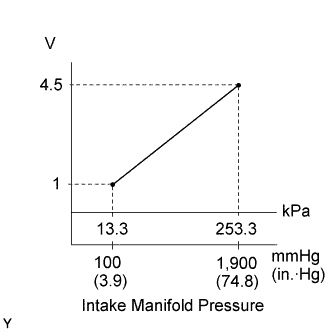
The turbo pressure sensor is connected to the intake manifold. The ECM detects the intake manifold pressure as a voltage by the sensor. The ECM uses the intake manifold pressure signal for correction of injection volume control and injection timing control.
The VSV for turbo pressure sensor switches the atmosphere applied to the turbo pressure sensor to the intake manifold pressure. The turbo pressure sensor monitors both the atmospheric pressure and intake manifold pressure and transmits the output voltage to the ECM, and the ECM uses this atmospheric pressure value for correcting the injection volume.
| DTC No. | DTC Detecting Condition | Trouble Area |
| 35 | Open or short in turbo pressure sensor circuit for 2 sec. or more |
|
Tech Tips
After confirming DTC No. 35, use the intelligent tester to confirm the intake manifold pressure from the CURRENT DATA.
| Intake Manifold Pressure (kPa) | Malfunction |
| Approx. 0 |
|
| 250 or more |
|
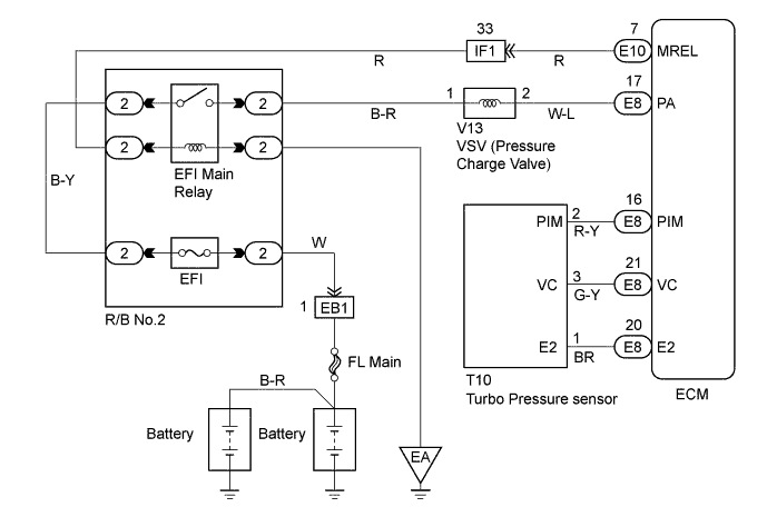
WIRING DIAGRAM
INSPECTION PROCEDURE
Tech Tips
-
If DTC Nos. 22, 24, 35 and 39 are output simultaneously, E2 (sensor ground) may be open.
-
Read freeze frame data using intelligent tester. Because freeze frame records the engine conditions when the malfunction is detected. When troubleshooting it is useful for determining whether the vehicle was running or stopped, the engine was warmed up or not, the air-fuel ratio was lean or rich, etc. at the time of the malfunction.
-
When not using the intelligent tester go to step 12.
PROCEDURE
-
READ VALUE OF INTELLIGENT TESTER (INTAKE MANIFOLD PRESSURE)
-
Connect the intelligent tester to the DLC3.
-
Turn the ignition switch ON and push the intelligent tester main switch ON.
-
Read the value of the intake manifold pressure on the intelligent tester.
Pressure Same as atmospheric pressure.
OK 
CHECK VACUUM HOSE (TURBO PRESSURE SENSOR - VSV FOR TURBO PRESSURE SENSOR) (VSV FOR TURBO PRESSURE SENSOR - INTAKE MANIFOLD) Click here
NG 
-
-
CHECK DIESEL TURBO TURBO PRESSURE SENSOR
- SST
- 09992-00242
-
Inspect the power source voltage of the turbo pressure sensor.
-
Disconnect the sensor connector.
-
Turn the ignition switch ON.
-
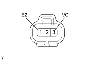
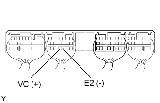
Using a voltmeter, measure the voltage between connector terminals VC (3) and E2 (1) of the wiring harness side.
Voltage 4.5 - 5.5 V -
Turn the ignition switch OFF.
-
Reconnect the sensor connector.
-
-
Text in Illustration *a Vacuum Inspect the power output of the turbo pressure sensor.
-
Turn the ignition switch ON.
-
Disconnect the vacuum hose from the sensor.
-
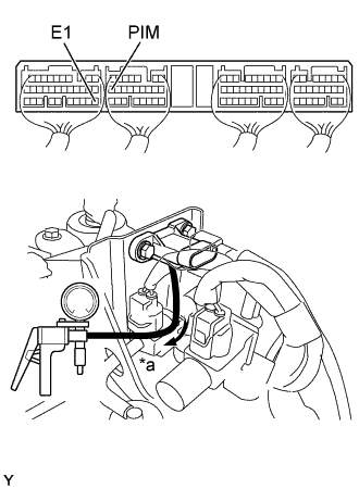
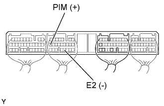
Connect a voltmeter to terminals PIM and E2 of the ECM (E8) connector, and measure the output voltage under ambient atmospheric pressure.
-
Apply vacuum to the sensor in 13.3 kPa (100 mmHg, 3.94 in.Hg) segments to 40.0 kPa (300 mmHg, 11.81 in.Hg).
-
Measure the voltage drop from step (4) above for each segment.
Voltage Applied vacuum
kPa (mmHg, in.Hg)
Voltage drop
V
13.3 (100, 3.94) 0.9 - 1.1 26.7 (200, 7.87) 1.1 - 1.3 40.0 (300, 11.81) 1.3 - 1.5 -
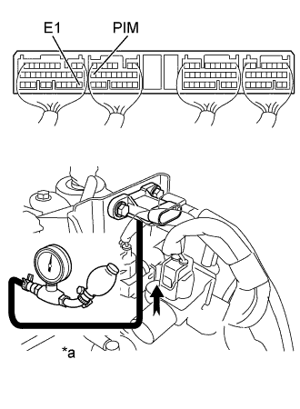
Text in Illustration *a Pressure Using SST (turbocharger pressure gauge), apply pressure to the sensor in 19.6 kPa (0.20 kgf/cm2, 2.84 psi) segments to 98.0 kPa (1.00 kgf/cm2, 14.2 psi).
-
Measure the voltage up from step (6) above for each segment.
Voltage up Applied pressure
kPa (kgf/cm2, psi)
Voltage up
V
39.2 (0.40, 5.69) 1.2 - 1.5 58.8 (0.60, 8.53) 1.5 - 1.8 78.5 (0.80, 11.4) 1.8 - 2.1 98.0 (1.00, 14.2) 2.1 - 2.4
-
NG 
REPLACE DIESEL TURBO TURBO PRESSURE SENSOR
OK
-
CHECK ECM (CHECK VOLTAGE)
-
Turn the ignition switch ON.
-
Check the voltage between terminals of the ECM connector as shown in the table and illustration.
Voltage Terminal
(Positive terminal ←→ Negative terminal)
Voltage VC (E8-21) ←→ E2 (E8-20) 4.5 - 5.5 V
NG
CHECK AND REPLACE ECM Click here
OK
-
-
CHECK ECM (CHECK VOLTAGE)
-
Turn the ignition switch ON.
-
Check the voltage between terminals of the ECM connector as shown in the table and illustration.
Voltage Terminal
(Positive terminal ←→ Negative terminal)
Voltage PIM (E8-16) ←→ E2 (E8-20) 1.7 - 2.9 V
OK
CHECK AND REPLACE ECM Click here
NG
CHECK WIRE HARNESS (ECM - VSV FOR TURBO PRESSURE SENSOR) (a) (VSV FOR TURBO PRESSURE SENSOR - BATTERY) (b) Click here
-
-
CHECK VACUUM HOSE (TURBO PRESSURE SENSOR - VSV FOR TURBO PRESSURE SENSOR) (VSV FOR TURBO PRESSURE SENSOR - INTAKE MANIFOLD)
NG
REPAIR OR REPLACE VACUUM HOSE
OK
-
CHECK VALVE, VACUUM SWITCHING
-

Text in Illustration *1 Ohmmeter Remove the VSV.
-
Inspect the VSV for open circuit.
-
Using an ohmmeter, check that the there is continuity between the terminals.
Resistance 33 - 39 Ω at 20°C (68°F)
-
-
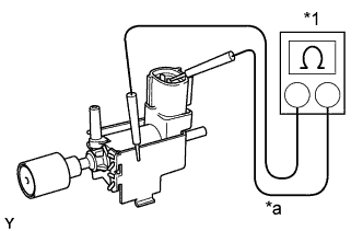
Text in Illustration *1 Ohmmeter *a No Continuity Inspect the VSV for ground.
-
Using an ohmmeter, check that there is no continuity between each terminal and the body.
-
-
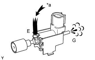
Text in Illustration *a Air Inspect the VSV operation.
-
Check that air does not flow from ports E to G.
-
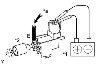
Text in Illustration *1 Battery *2 Filter *a Air Apply battery voltage across the terminals.
-
Check that air flows from port E to filter.
-
NG
REPLACE VALVE, VACUUM SWITCHING
OK
-
-
CHECK VALVE, VACUUM SWITCHING (CHECK FUNCTION)
-
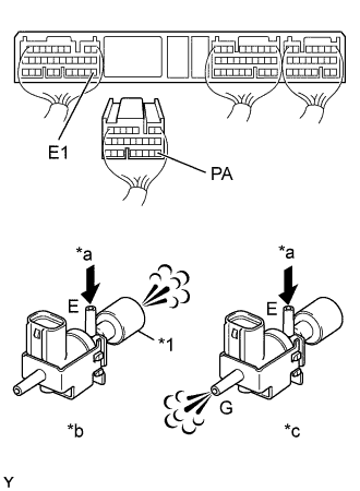
Text in Illustration *1 Air Filter *a Air *b VSV: ON *c VSV: OFF Disconnect the ECM (E8) connector.
-
Turn the ignition switch ON.
-
Check the VSV function.
-
Connect between terminal PA of the ECM (E8) connector and E1 of the ECM (E7) connector (VSV is ON).
-
Disconnect between terminal PA of the ECM (E8) connector and E1 of the ECM (E7) connector (VSV is OFF).
VSV is ON Air from port E flows out through the air filter. VSV is OFF Air from port E flows out through port G.
OK
CHECK TURBOCHARGER SUB-ASSEMBLY Click here
NG
-
-
CHECK WIRE HARNESS (ECM - VSV FOR TURBO PRESSURE SENSOR) (a) (VSV FOR TURBO PRESSURE SENSOR - BATTERY) (b)
-
Check for open and short in harness and connector between the ECM and VSV for turbo pressure sensor.
-
Disconnect the VSV for turbo pressure sensor connector.
-
Disconnect the ECM (E8) connector.
-
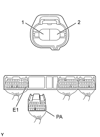
Check the continuity between terminals of the VSV for turbo pressure sensor and ECM connectors as shown in the illustration and table.
Continuity (Check for open) Terminal
(VSV for turbo pressure sensor ←→ ECM)
Standard 2 ←→ PA (E8-17) Continuity Continuity (Check for short) Terminal
(ECM ←→ ECM(Ground))
Standard PA (E8-17) ←→ E1 (E7-22) No continuity
-
-
To check wire harness for terminal 1 of the VSV for turbo pressure sensor connector, refer to the wiring diagram.
OK
REPLACE VALVE, VACUUM SWITCHING
NG
REPAIR HARNESS AND CONNECTOR
-
-
CHECK TURBOCHARGER SUB-ASSEMBLY
NG
REPLACE TURBOCHARGER SUB-ASSEMBLY
OK
-
CHECK ELECTRIC EGR CONTROL VALVE ASSEMBLY
NG
REPLACE ELECTRIC EGR CONTROL VALVE ASSEMBLY
OK
-
CHECK INTAKE MASS AIR FLOW METER ASSEMBLY
-
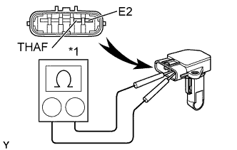
Text in Illustration *1 Ohmmeter Remove the air flow meter.
-
Using an ohmmeter, measure the resistance between terminals THAF and E2.
Terminals Resistance Temperature THAF (4) ←→ E2 (5) 12.5 - 16.9 kΩ -20°C (-4°F) THAF (4) ←→ E2 (5) 2.19 - 2.67 kΩ 20°C (68°F) THAF (4) ←→ E2 (5) 0.50 - 0.68 kΩ 60°C (140°F) -
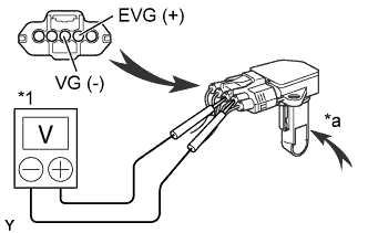
Text in Illustration *1 Voltmeter *a Air Inspect for operation.
-
Connect the air flow meter connector.
-
Connect the negative (-) terminal cable to the battery.
-
Turn the ignition switch ON.
-
Using a voltmeter, connect the positive (+) tester probe to terminal VG, and negative (-) tester probe to terminal EVG.
-
Blow air into the air flow meter, and check that the voltage fluctuates.
-
NG
REPLACE INTAKE MASS AIR FLOW METER ASSEMBLY
OK 
CHECK AND REPLACE ECM Click here
-
-
CHECK DIESEL TURBO TURBO PRESSURE SENSOR
- SST
- 09992-00242
-
Inspect the power source voltage of the turbo pressure sensor.
-
Disconnect the sensor connector.
-
Turn the ignition switch ON.
-
Using a voltmeter, measure the voltage between connector terminals VC and E2 of the wiring harness side.
Voltage 4.5 - 5.5 V -
Turn the ignition switch OFF.
-
Reconnect the sensor connector.
-
-
Text in Illustration *a Vacuum Inspect the power output of the turbo pressure sensor.
-
Turn the ignition switch ON.
-
Disconnect the vacuum hose from the sensor.
-
Connect a voltmeter to terminals PIM and E2 of the ECM, and measure the output voltage under ambient atmospheric pressure.
-
Apply vacuum to the sensor in 13.3 kPa (100 mmHg, 3.94 in.Hg) segments to 40.0 kPa (300 mmHg, 11.81 in.Hg).
-
Measure the voltage drop from step (4) above for each segment.
Voltage drop Applied vacuum
kPa (mmHg, in.Hg)
Voltage drop
V
13.3 (100, 3.94) 0.9 - 1.1 26.7 (200, 7.87) 1.1 - 1.3 40.0 (300, 11.81) 1.3 - 1.5 -
Text in Illustration *a Pressure Using SST (turbocharger pressure gauge), apply pressure to the sensor in 19.6 kPa (0.20 kgf/cm2, 2.84 psi) segments to 98.0 kPa (1.00 kgf/cm2, 14.2 psi).
-
Measure the voltage up from step (c) above for each segment.
Voltage up Applied pressure
kPa (kgf/cm2, psi)
Voltage up
V
39.2 (0.40, 5.69) 1.2 - 1.5 58.8 (0.60, 8.53) 1.5 - 1.8 78.5 (0.80, 11.4) 1.8 - 2.1 98.0 (1.00, 14.2) 2.1 - 2.4
-
NG
REPLACE DIESEL TURBO TURBO PRESSURE SENSOR
OK
-
CHECK ECM (CHECK VOLTAGE)
-
Turn the ignition switch ON.
-
Check the voltage between the terminals of shown in the table and illustration.
Voltage Terminal
(Positive terminal ←→ Negative terminal)
Voltage VC (E8-21) ←→ E2 (E8-20) 4.5 - 5.5 V
NG
CHECK AND REPLACE ECM Click here
OK
-
-
CHECK ECM (CHECK VOLTAGE)
-
Turn the ignition switch ON.
-
Check the voltage between the terminals of the ECM connector as shown in the table and illustration.
Voltage Terminal
(Positive terminal ←→ Negative terminal)
Voltage PIM (E8-16) ←→ E2 (E8-20) 1.7 - 2.9 V
OK
CHECK AND REPLACE ECM Click here
NG
-
-
CHECK WIRE HARNESS (ECM - TURBO PRESSURE SENSOR)
-
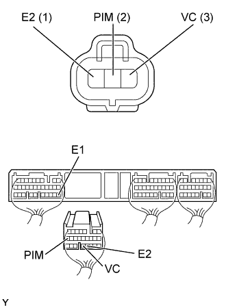
Disconnect the turbo pressure sensor connector.
-
Disconnect the ECM (E8) connector.
-
Check the continuity between the terminals of the turbo pressure sensor and ECM connectors as shown in the illustration and table.
Continuity (Check for open) Terminal
(Turbo pressure sensor ←→ ECM)
Standard PIM (2) ←→ PIM (E8-16) Continuity VC (3) ←→ VC (E8-21) E2 (1) ←→ E2 (E8-20) Continuity (Check for short) Terminal
(ECM ←→ ECM(Ground))
Standard PIM (E8-16) ←→ E1 (E7-22) No continuity VC (E8-21) ←→ E1 (E7-22)
NG
REPAIR OR REPLACE HARNESS AND CONNECTOR
OK
-
-
CHECK VACUUM HOSE (TURBO PRESSURE SENSOR - VSV FOR TURBO PRESSURE SENSOR) (VSV FOR TURBO PRESSURE SENSOR - INTAKE MANIFOLD)
NG
REPAIR OR REPLACE HARNESS AND CONNECTOR
OK
-
CHECK VALVE, VACUUM SWITCHING
-
Text in Illustration *1 Ohmmeter Remove the VSV.
-
Inspect the VSV for open circuit.
-
Using an ohmmeter, check that the there is continuity between the terminals.
Resistance 33 - 39 Ω at 20°C (68°F)
-
-
Text in Illustration *1 Ohmmeter *a No Continuity Inspect the VSV for ground.
-
Using an ohmmeter, check that there is no continuity between each terminal and the body.
-
-
Text in Illustration *a Air Inspect the VSV operation.
-
Check that air does not flow from ports E to G.
-
Text in Illustration *1 Battery *2 Filter *a Air Apply battery voltage across the terminals.
-
Check that air flows from port E to filter.
-
NG
REPLACE VALVE, VACUUM SWITCHING
OK
-
-
CHECK VALVE, VACUUM SWITCHING (CHECK FUNCTION)
-
Text in Illustration *1 Air Filter *a Air *b VSV: ON *c VSV: OFF Disconnect the ECM (E8) connector.
-
Turn the ignition switch ON.
-
Check the VSV function.
-
Connect between terminal PA of the ECM (E8) connector and E1 of the ECM (E7) connector (VSV is ON).
-
Disconnect between terminal PA of the ECM (E8) connector and E1 of the ECM (E7) connector (VSV is OFF).
VSV is ON Air from port E flows out through the air filter. VSV is OFF Air from port E flows out through port G.
OK
CHECK WIRE HARNESS (ECM - VSV FOR TURBO PRESSURE SENSOR) (a) (VSV FOR TURBO PRESSURE SENSOR - BATTERY) (b) Click here
NG
-
-
CHECK TURBOCHARGER SUB-ASSEMBLY
NG
REPLACE TURBOCHARGER SUB-ASSEMBLY
OK
-
CHECK ELECTRIC EGR CONTROL VALVE ASSEMBLY
NG
REPLACE ELECTRIC EGR CONTROL VALVE ASSEMBLY
OK
-
CHECK INTAKE MASS AIR FLOW METER ASSEMBLY
-
Text in Illustration *1 Ohmmeter Remove the air flow meter.
-
Using an ohmmeter, measure the resistance between terminals THAF and E2.
Terminals Resistance Temperature THAF (4) ←→ E2 (5) 12.5 - 16.9 kΩ -20°C (-4°F) THAF (4) ←→ E2 (5) 2.19 - 2.67 kΩ 20°C (68°F) THAF (4) ←→ E2 (5) 0.50 - 0.68 kΩ 60°C (140°F) -
Text in Illustration *1 Voltmeter *a Air Inspect for operation.
-
Connect the air flow meter connector.
-
Connect the negative (-) terminal cable to the battery.
-
Turn the ignition switch ON.
-
Using a voltmeter, connect the positive (+) tester probe to terminal VG, and negative (-) tester probe to terminal EVG.
-
Blow air into the air flow meter, and check that the voltage fluctuates.
-
OK
CHECK AND REPLACE ECM Click here
NG
REPLACE INTAKE MASS AIR FLOW METER ASSEMBLY
-
-
CHECK WIRE HARNESS (ECM - VSV FOR TURBO PRESSURE SENSOR) (a) (VSV FOR TURBO PRESSURE SENSOR - BATTERY) (b)
-
Check for open and short in harness and connector between the ECM and VSV for turbo pressure sensor.
-
Disconnect the VSV for turbo pressure sensor connector.
-
Disconnect the ECM (E8) connector.
-
Check the continuity between terminals of the VSV for turbo pressure sensor and ECM connectors as shown in the illustration and table.
Continuity (Check for open) Terminal
(VSV for turbo pressure sensor ←→ ECM)
Standard 2 ←→ PA (E8-17) Continuity Continuity (Check for short) Terminal
(ECM ←→ ECM(Ground))
Standard PA (E8-17) ←→ E1 (E7-22) No continuity
-
-
To check wire harness for terminal 1 of the VSV for turbo pressure sensor connector, refer to the wiring diagram.
NG
REPAIR HARNESS AND CONNECTOR
OK
CHECK AND REPLACE ECM Click here
-