ECD SYSTEM, Diagnostic DTC:33(1), 33(2)
| DTC Code | DTC Name |
|---|---|
| 33(1) | Exhaust Gas Control System Malfunction |
| 33(2) | Exhaust Gas Control System Malfunction |
DESCRIPTION
DTC No. 33 (1):
The ECM fully closes the exhaust control valve via the VSV when the warm up switch is ON. This makes it possible to increase the engine load and then maintain the high temperature of the exhaust gas. As a result, the engine water temperature increases.
Outer temperature, water temperature, the number of engine revolution and injection volume while the engine is running, are the conditions to fully close the valve. The valve, however, will once fully close then fully open, regardless of any conditions whenever the ignition switch is turned OFF and the vehicle's speed is 0 km/h.
If the valve becomes unable to operate, owing to being stuck or other factors, while the valve is fully closed, the ECM will output DTC No. 33 (1) by detecting a signal from the turbo pressure. At this time, the engine check lamp starts blinking.
DTC No. 33 (2):
When the warm up switch is ON, the exhaust control valve is close the pressure goes up too high, because a foreign object is stuck or for other reasons, the ECM detects it and forces the exhaust control valve to fully open. At this time, DTC No. 33 (2) is output but the engine check lamp does not blink.
| DTC No. | DTC Detecting Condition | Trouble Area |
| 33(1) | Exhaust control valve fully closed can not be operate |
|
| 33(2) | Exhaust control valve does not fully closed (Clearance is clogged) |
|
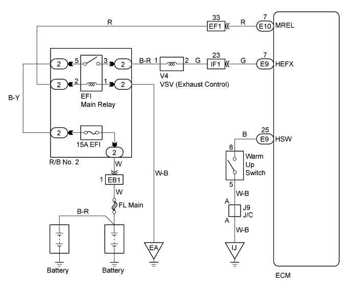
WIRING DIAGRAM
INSPECTION PROCEDURE
Tech Tips
-
Read freeze frame data using intelligent tester. Because freeze frame records the engine conditions when the malfunction is detected. When troubleshooting it is useful for determining whether the vehicle was running or stopped, the engine was warmed up or not, the air-fuel ratio was lean or rich, etc. at the time of the malfunction.
-
When not using the intelligent tester go to step 12.
PROCEDURE
-
CHECK EXHAUST GAS CONTROL VALVE ASSEMBLY
-
Check the exhaust control valve operation Click here .
NG 
REPAIR OR REPLACE EXHAUST GAS CONTROL VALVE ASSEMBLY
OK 
-
-
PERFORM ACTIVE TEST BY INTELLIGENT TESTER (CHECK EXHAUST GAS CONTROL VALVE ASSEMBLY)
OK 
CHECK CONNECTION OF HOSE (VACUUM HOSE TO TURBO PRESSURE SENSOR) Click here
NG
-
CHECK CONNECTION OF HOSE (TO VACUUM SWITCHING VALVE)
NG
REPAIR OR REPLACE VACUUM HOSE
OK
-
PERFORM ACTIVE TEST BY INTELLIGENT TESTER (VACUUM SWITCHING VALVE)
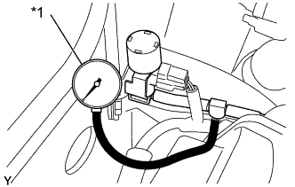
Text in Illustration *1 Vacuum Gauge
-
Using a 3-way connector, connect a vacuum gauge to the hose between the VSV and exhaust control valve.
-
Warm up the engine to above 80°C (176°F).
-
Engine at idling
-
Connect the intelligent tester to the DLC3.
-
Turn the ignition switch ON and the push the intelligent tester main switch is ON.
-
Select the ACTIVE TEST mode on the intelligent tester.
-
Check the vacuum when VSV is operated by intelligent tester.
Result VSV Vacuum ON 0 kPa (0 mmHg, 0 in. Hg) OFF Above 28 kPa (210 mmHg, 8.3 in. Hg)
OK
CHECK CONNECTION OF HOSE (AIR INLET HOSE FROM TURBOCHARGER) Click here
NG
-
-
CHECK ECM (CHECK VOLTAGE)
-
Turn the ignition switch ON.
-
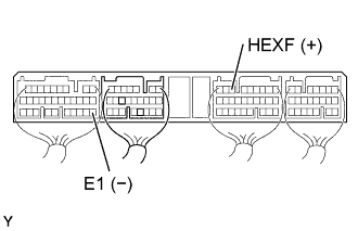
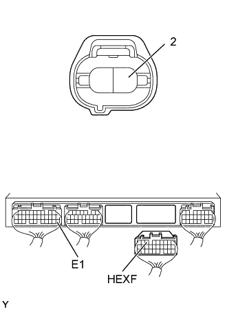
Check the voltage between terminals of the ECM connector as shown in the table and illustration.
Voltage Terminal
(Positive terminal ←→ Negative terminal)
Voltage HEXF (E9-7) ←→ E1 (E7-22) 4.5 - 5.5 V
NG
CHECK AND REPLACE ECM Click here
OK
-
-
PERFORM ACTIVE TEST BY INTELLIGENT TESTER (VACUUM SWITCHING VALVE)
-
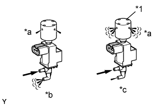
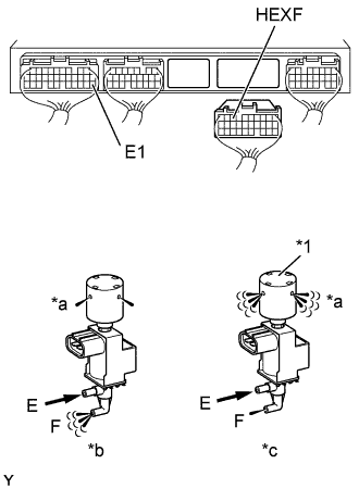
Text in Illustration *1 Air Filter *a Air *b VSV: ON *c VSV: OFF Disconnect the vacuum hoses from the VSV.
-
Connect the intelligent tester to the DLC3.
-
Turn the ignition switch ON and push the intelligent tester main switch ON.
-
Select the ACTIVE TEST mode on the intelligent tester.
-
Check the operation of the VSV when it is operated by the intelligent tester.
Result VSV is ON Air from port E flows out through port F. VSV is OFF Air from port E flows out through air filter.
OK
CHECK AND REPLACE EXHAUST GAS CONTROL VALVE ASSEMBLY
NG
-
-
INSPECT VACUUM SWITCHING VALVE
-
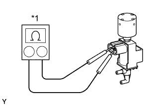
Text in Illustration *1 Ohmmeter Inspect the VSV for open circuit.
-
Using an ohmmeter, measure the resistance between terminals as shown.
Resistance 33 - 39 Ω at 20°C (68°F)
-
-
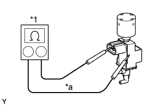
Text in Illustration *1 Ohmmeter *a No Continuity Inspect the VSV for ground.
-
Using an ohmmeter, check that there is no continuity between terminals and VSV body.
-
-
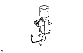
Text in Illustration *a Vacuum Inspect the VSV for air tightness.
-
Check that when vacuum is applied to the vacuum outlet port shown, the needle of vacuum pump indicates an increase of 66.7 kPa (500 mmHg, 19.7 in. Hg) or more.
-
-
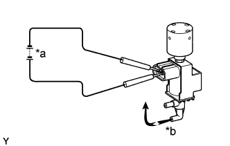
Text in Illustration *a 6 V *b Vacuum Inspect the VSV operation.
-
Apply about 6 V of DC power to the terminals.
-
Check that when vacuum is applied to the vacuum outlet port shown, the need does not move.
-
NG
REPLACE VACUUM SWITCHING VALVE
OK
-
-
CHECK WIRE HARNESS (ECM - VSV) (a) (VSV - EFI MAIN RELAY (MARKING EFI)) (b)
-
Check for open and short in harness and connector between ECM and VSV.
-
Disconnect the VSV connector.
-
Disconnect the ECM (E9) connector.
-
Check the continuity between the terminals VSV and ECM connector as shown in the illustration and table.
Continuity (Check for open) Terminal
(VSV ←→ ECM)
Standard 2 ←→ HEXF (E9-7) Continuity Continuity (Check for short) Terminal
(ECM ←→ ECM(Ground))
Standard HEXF (E9-2) ←→ E1 (E7-22) No continuity
-
-
Check for open and short in harness and connector between the VSV and EFI main relay.
-
Remove the EFI main relay.
-
Disconnect the engine VSV connector.
-
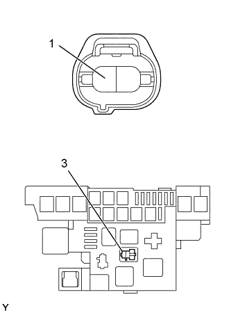
Check the continuity between the terminals VSV and EFI main relay of R/B No. 2 (3) as shown in the illustration and table.
Standard (Check for open) Terminal
(EFI main relay of R/B No. 2 ←→ VSV)
Standard 3 ←→ 1 Continuity -
Check the continuity between the terminals VSV and body ground as shown in the illustration and table.
Standard (Check for short) Terminal
(VSV ←→ Ground)
Standard 1 ←→ Body ground No continuity
-
NG
REPAIR OR REPLACE HARNESS AND CONNECTOR
OK
-
-
CHECK EXHAUST GAS CONTROL VALVE ASSEMBLY
-
Check that no foreign object exists in the exhaust control valve.
NG
REPAIR OR REPLACE EXHAUST GAS CONTROL VALVE ASSEMBLY
OK
-
-
CHECK CONNECTION OF HOSE (AIR INLET HOSE FROM TURBOCHARGER)
NG
REPAIR OR REPLACE AIR HOSE
OK
-
CHECK CONNECTION OF HOSE (VACUUM HOSE TO TURBO PRESSURE SENSOR)
NG
REPAIR OR REPLACE VACUUM HOSE
OK 
CHECK AND REPLACE ECM Click here
-
CHECK EXHAUST GAS CONTROL VALVE ASSEMBLY
-
Check the exhaust control valve operation Click here.
NG
REPAIR OR REPLACE EXHAUST GAS CONTROL VALVE ASSEMBLY
OK
-
-
CHECK CONNECTION OF HOSE (TO VACUUM SWITCHING VALVE)
NG
REPAIR OR REPLACE VACUUM HOSE
OK
-
CHECK VACUUM
Text in Illustration *1 Vacuum Gauge
-
Using a 3-way connector, connect a vacuum gauge to the hose between the VSV and exhaust control valve.
-
Warm up the engine to above 80°C (176°F).
-
Engine at idling.
-
EGR system is ON.
Result Warm up switch Vacuum ON 0 kPa (0 mmHg, 0 in. Hg) OFF Above 28 kPa (210 mmHg, 8.3 in. Hg)
OK
CHECK CONNECTION OF HOSE (VACUUM HOSE TO TURBO PRESSURE SENSOR) Click here
NG
-
-
CHECK ECM (CHECK VOLTAGE)
-
Turn the ignition switch ON.
-
Check the voltage between terminals of the ECM connector as shown in the table and illustration.
Voltage Terminal
(Positive terminal ←→ Negative terminal)
Voltage HEXF (E9-7) ←→ E1 (E7-22) 4.5 - 5.5 V
NG
CHECK AND REPLACE ECM Click here
OK
-
-
CHECK VACUUM SWITCHING VALVE (CHECK FUNCTION)
-
Text in Illustration *1 Air Filter *a Air *b VSV: ON *c VSV: OFF Disconnect the (E9) connector from the ECM.
-
Turn the ignition switch ON.
-
Check the VSV operation.
-
Connect between terminal HEXF and E1 of the ECM (E9) and (E7) connector (ON).
-
Disconnect between terminal HEXF and E1 of the ECM (E9) and (E7) connector (OFF).
VSV ON Air from port E flows out through port F. VSV OFF Air from port E flows out through air filter. -
OK
CHECK AND REPLACE EXHAUST GAS CONTROL VALVE ASSEMBLY
NG
-
-
INSPECT VACUUM SWITCHING VALVE
-
Text in Illustration *1 Ohmmeter Inspect the VSV for open circuit.
-
Using an ohmmeter, measure the resistance between terminals as shown.
Resistance 33 - 39 Ω at 20°C (68°F)
-
-
Text in Illustration *1 Ohmmeter *a No Continuity Inspect the VSV for ground.
-
Using an ohmmeter, check that there is no continuity between terminals and VSV body.
-
-
Text in Illustration *a Vacuum Inspect the VSV for air tightness.
-
Check that when vacuum is applied to the vacuum outlet port shown, the needle of vacuum pump indicates an increase of 66.7 kPa (500 mmHg, 19.7 in. Hg) or more.
-
-
Text in Illustration *a 6 V *b Vacuum Inspect the VSV operation.
-
Apply about 6 V of DC power to the terminals.
-
Check that when vacuum is applied to the vacuum outlet port shown, the need does not move.
-
NG
REPLACE VACUUM SWITCHING VALVE
OK
-
-
CHECK WIRE HARNESS (ECM - VSV) (a) (VSV - EFI MAIN RELAY (MARKING EFI)) (b)
-
Check for open and short in harness and connector between ECM and VSV.
-
Disconnect the VSV connector.
-
Disconnect the ECM (E9) connector.
-
Check the continuity between the terminals VSV and ECM connector as shown in the illustration and table.
Continuity (Check for open) Terminal
(VSV ←→ ECM)
Standard 2 ←→ HEXF (E9-7) Continuity Continuity (Check for short) Terminal
(ECM ←→ ECM(Ground))
Standard HEXF (E9-2) ←→ E1 (E7-22) No continuity
-
-
Check for open and short in harness and connector between the VSV and EFI main relay.
-
Remove the EFI main relay.
-
Disconnect the engine VSV connector.
-
Check the continuity between the terminals VSV and EFI main relay of R/B No. 2 (3) as shown in the illustration and table.
Standard (Check for open) Terminal
(EFI main relay of R/B No. 2 ←→ VSV)
Standard 3 ←→ 1 Continuity -
Check the continuity between the terminals VSV and body ground as shown in the illustration and table.
Standard (Check for short) Terminal
(VSV ←→ Ground)
Standard 1 ←→ Body ground No continuity
-
NG
REPAIR OR REPLACE HARNESS AND CONNECTOR
OK
-
-
CHECK EXHAUST GAS CONTROL VALVE ASSEMBLY
-
Check that no foreign object exists in the exhaust control valve Click here.
NG
REPAIR OR REPLACE EXHAUST GAS CONTROL VALVE ASSEMBLY
OK
-
-
CHECK CONNECTION OF HOSE (AIR INLET HOSE FROM TURBOCHARGER)
NG
REPAIR OR REPLACE AIR HOSE
OK
-
CHECK CONNECTION OF HOSE (VACUUM HOSE TO TURBO PRESSURE SENSOR)
NG
REPAIR OR REPLACE VACUUM HOSE
OK
CHECK AND REPLACE ECM Click here