ECD SYSTEM, Diagnostic DTC:31
| DTC Code | DTC Name |
|---|---|
| 31 | Air Flow Circuit Malfunction |
DESCRIPTION
The air flow meter uses a platinum hot wire. The hot wire air flow meter consists of a platinum hot wire, thermistor and a control circuit installed in a plastic housing. The hot wire air flow meter works on the principle that the hot wire and thermistor located in the intake air bypass of the housing detect any changes in the intake air temperature.
The hot wire is maintained at the set temperature by controlling the current flow through the hot wire. This current flow is then measured as the output voltage of the air flow meter.
The circuit is constructed so that the platinum hot wire and thermistor provide a bridge circuit with the power transistor controlled so that the potential of A and B remains equal to maintain the set temperature.
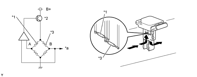
| *1 | Thermistor | *2 | Power Transistor |
| *3 | Platinum Hot Wire | - | - |
| *a | Output Voltage | - | - |
| DTC No. | DTC Detecting Condition | Trouble Area |
| 31 | Open or short in air flow meter circuit with more than 3 sec. |
|
Tech Tips
After confirming DTC No. 31, use the intelligent tester to confirm the air flow ratio from the CURRENT DATA.
| Air Flow Value (gm/sec) | Malfunction |
| Approx. 0.0 |
|
| 184.0 or more |
|
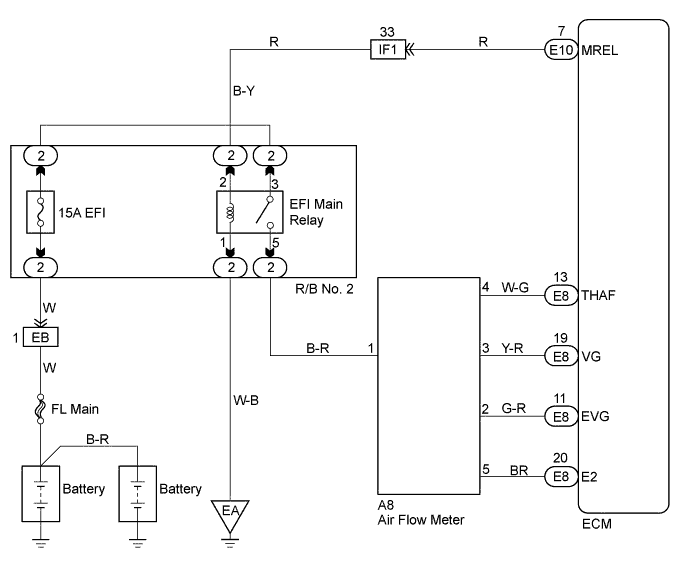
WIRING DIAGRAM
INSPECTION PROCEDURE
Tech Tips
-
Read freeze frame data using intelligent tester. Because freeze frame records the engine conditions when the malfunction is detected. When troubleshooting, it is useful for determining whether the vehicle was running or stopped, the engine was warmed up or not, the air-fuel ratio was lean or rich, etc. at the time of the malfunction.
-
When not using the intelligent tester go to step 7.
PROCEDURE
-
READ VALUE OF INTELLIGENT TESTER (AIR FLOW RATE)
-
Connect the intelligent tester to the DLC3.
-
Turn the ignition switch ON and push the intelligent tester main switch ON.
-
Start the engine.
-
Read the air flow rate on the intelligent tester.
Type 1 Type 2 Air Flow Rata (gm/sec.) 0.0 271.0 or more
Type2 
CHECK ECM (CHECK CONTINUITY) Click here
Type1 
-
-
CHECK INTAKE MASS AIR FLOW METER ASSEMBLY (POWER SOURCE VOLTAGE)
-
Disconnect the air flow meter connector.
-
Turn the ignition switch ON.
-
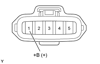
Check the voltage between terminals of the air flow meter connector as shown in the table and illustration.
Voltage Terminal
(Positive terminal ←→ Negative terminal)
Voltage +B (1) ←→ Body ground 9 - 14V
NG 
CHECK WIRE HARNESS
OK
-
-
CHECK ECM (CHECK VOLTAGE)
-
Inspect the ECU power source circuit Click here.
-
Start the engine.
-
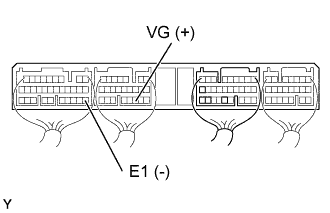
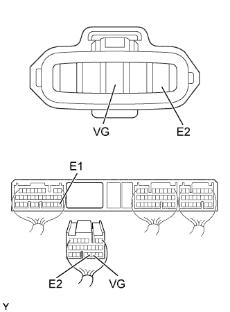
Check the voltage between terminals of the ECM connector as shown in the table and illustration.
Voltage (Neutral position) Terminal
(Positive terminal ←→ Negative terminal)
Voltage VG (E8-19) ←→ E1 (E7-22) 0.5 - 3.0 V
OK
CHECK AND REPLACE ECM Click here
NG
-
-
CHECK WIRE HARNESS (ECM - AIR FLOW METER)
-
Disconnect the air flow meter connector.
-
Disconnect the ECM (E8) connector.
-
Check the continuity between terminals of the air flow meter and ECM connectors as shown in the illustration and table.
Continuity (Check for open) Terminal
(Air flow meter ←→ ECM)
Standard VG (3) ←→ VG (E8-19) Continuity E2 (5) ←→ E2 (E8-20) Continuity (Check for short) Terminal
(ECM ←→ ECM(Ground))
Standard VG (E8-19) ←→ E1 (E7-22) No continuity
NG
REPAIR OR REPLACE HARNESS AND CONNECTOR
OK 
REPLACE INTAKE MASS AIR FLOW METER ASSEMBLY
-
-
CHECK ECM (CHECK CONTINUITY)
-
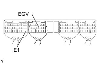
Check the continuity between terminals of the ECM connectors as shown in the illustration and table.
Continuity (Check for short) Terminal
(ECM ←→ ECM(Ground))
Standard EVG (E8-11) ←→ E1 (E7-22) Continuity
(1 Ω or less)
NG
CHECK AND REPLACE ECM Click here
OK
-
-
CHECK WIRE HARNESS (ECM - AIR FLOW METER)
-
Disconnect the air flow meter connector.
-
Disconnect the ECM (E8) connector.
-
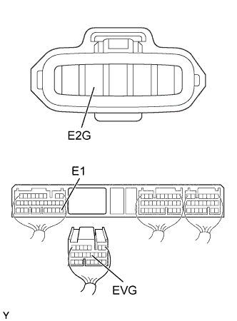
Check the continuity between terminals of the air flow meter and ECM connectors as shown in the illustration and table.
Continuity (Check for open) Terminal
(Air flow meter ←→ ECM)
Standard E2G (2) ←→ EVG (E8-11) Continuity Continuity (Check for short) Terminal
(ECM ←→ ECM(Ground))
Standard EVG (E8-11) ←→ E1 (E7-22) No continuity
NG
REPAIR OR REPLACE HARNESS AND CONNECTOR
OK
REPLACE INTAKE MASS AIR FLOW METER ASSEMBLY
-
-
CHECK ECM (CHECK VOLTAGE)
-
Inspect ECU power source circuit Click here
-
Start the engine.
-
Check the voltage between terminals of ECM connector as shown in the table and illustration.
Voltage (Neutral position) Terminal
(Positive terminal ←→ Negative terminal)
Voltage VG (E8-19) ←→ E1 (E7-22) 0.5 - 3.0 V
OK
CHECK AND REPLACE ECM Click here
NG
-
-
CHECK INTAKE MASS AIR FLOW METER ASSEMBLY (POWER SOURCE VOLTAGE)
-
Disconnect the air flow meter connector.
-
Turn the ignition switch ON.
-
Check the voltage between terminals of the air flow meter connector as shown in the table and illustration.
Voltage Terminal
(Positive terminal ←→ Negative terminal)
Voltage +B (1) ←→ Body ground 9 - 14V
NG
CHECK WIRE HARNESS
OK
-
-
CHECK WIRE HARNESS (ECM - AIR FLOW METER)
-
Disconnect the air flow meter connector.
-
Disconnect the ECM (E8) connector.
-
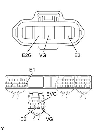
Check the continuity between terminals of the air flow meter and ECM connectors as shown in the illustration and table.
Continuity (Check for open) Terminal
(Air flow meter ←→ ECM)
Standard VG (3) ←→ VG (E8-19) Continuity E2 (5) ←→ E2 (E8-20) E2G (2) ←→ EVG (E8-11) Continuity (Check for short) Terminal
(ECM ←→ ECM(Ground))
Standard VG (E8-19) ←→ E1 (E7-22) No continuity EVG (E8-11) ←→ E1 (E7-22)
NG
REPAIR OR REPLACE HARNESS AND CONNECTOR
OK
REPLACE INTAKE MASS AIR FLOW METER ASSEMBLY
-