ECD SYSTEM, Diagnostic DTC:19(2)
| DTC Code | DTC Name |
|---|---|
| 19(2) | Accelerator Pedal Position Sensor Circuit Mulfunction (Idle Switch/Range) |
DESCRIPTION
Refer to DTC No. 19 (1) on page Click here.
| DTC No. | DTC Detecting Condition | Trouble Area |
| 19(2) | Either the ECU sensor completed learning and when the electric potential difference of No. 1 and No. 2 sensors has become more than 1.2 V or less than 0.4 V. |
|
| Either one of the followings continues more than 2.0 seconds. When the electrical potential difference of No. 1 and No. 2 sensors is beside the specified value. (a) VPA2 is 4.9 V or more. (b) Accelerator idling criterion voltage of No. 1 and No. 2 in less than 0.04 V. |
WIRING DIAGRAM
Refer to DTC No. 19 (1) on page Click here.
INSPECTION PROCEDURE
Tech Tips
Read freeze frame data using intelligent tester. Because freeze frame records the engine conditions when the malfunction is detected. When troubleshooting it is useful for determining whether the vehicle was running or stopped, the engine was warmed up or not, the air-fuel ratio was lean or rich, etc. at the time of the malfunction.
PROCEDURE
-
CHECK ACCELERATOR LINK ASSEMBLY (CHECK VOLTAGE)
-
Disconnect the accelerator pedal position sensor connector.
-
Turn the ignition switch ON.
-
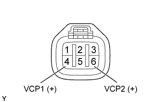
Check the voltage between terminals of the accelerator pedal position sensor connector as shown in the table and illustration.
Voltage Terminal
(Positive terminal ←→ Negative terminal)
Voltage VCP1 (4) ←→ Body ground 4.5 - 5.5 V VCP2 (6) ←→ Body ground
NG 
CHECK ECM (CHECK VOLTAGE) Click here
OK 
-
-
CHECK ECM (CHECK VOLTAGE)
-
Turn the ignition switch ON.
-
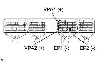
Check the voltage between terminals of the ECM connector as shown in the table and illustration.
Voltage Accelerator pedal Terminal
(Positive terminal ←→ Negative terminal)
Voltage Fully closed VPA1 (E9-19) ←→ EP1 (E9-27) 0.5 - 1.1 V VPA2 (E9-28) ←→ EP2 (E9-24) 0.9 - 2.3 V Fully open VPA1 (E9-19) ←→ EP1 (E9-27) 3.0 - 4.6 V VPA2 (E9-28) ←→ EP2 (E9-24) 3.4 - 5.0 V
OK 
CHECK AND REPLACE ECM Click here
NG
-
-
CHECK WIRE HARNESS (ECM - ACCELERATOR PEDAL POSITION SENSOR)
-
Disconnect the accelerator pedal position sensor connector.
-
Disconnect the ECM (E9) connector.
-
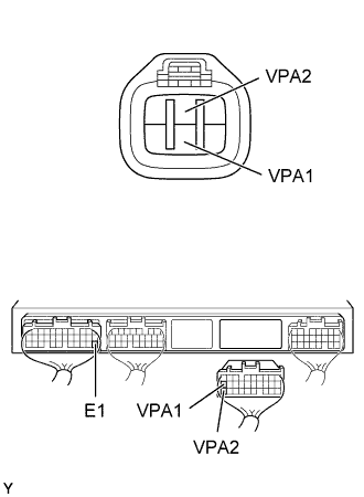
Check the continuity between terminals of the accelerator pedal position sensor and ECM connectors as shown in the illustration and table.
Continuity (Check for open) Terminal
(Accelerator pedal position sensor ←→ ECM)
Standard VPA1 (5) ←→ VPA1 (E9-19) Continuity VPA2 (2) ←→ VPA2 (E9-28) Continuity (Check for short) Terminal
(ECM ←→ ECM(Ground))
Standard VPA1 (E9-19) ←→ E1 (E7-22) No continuity VPA2 (E9-28) ←→ E1 (E7-22)
NG
REPAIR OR REPLACE HARNESS AND CONNECTOR
OK 
REPAIR ACCELERATOR LINK ASSEMBLY
-
-
CHECK ECM (CHECK VOLTAGE)
-
Turn the ignition switch ON.
-
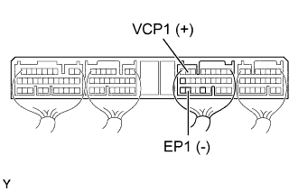
Check the voltage between terminals of the ECM connector as shown in the table and illustration.
Voltage Terminal
(Positive terminal ←→ Negative terminal)
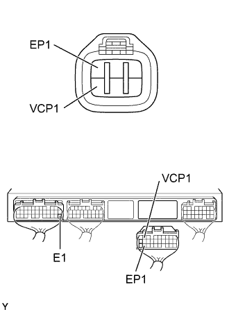
Voltage VCP1 (E9-8) ←→ EP1 (E9-27) 4.5 - 5.5 V
NG
CHECK AND REPLACE ECM Click here
OK
-
-
CHECK WIRE HARNESS (ECM - ACCELERATOR PEDAL POSITION SENSOR)
-
Disconnect the accelerator pedal position sensor connector.
-
Disconnect the ECM (E9) connector.
-
Check the continuity between terminals of the accelerator pedal position sensor and ECM connectors as shown in the illustration and table.
Continuity (Check for open) Terminal
(Accelerator pedal position sensor ←→ ECM)
Standard VCP1 (4) ←→ VCP1 (E9-8) Continuity EP1 (1) ←→ EP1(E9-27) Continuity (Check for short) Terminal
(ECM ←→ ECM(Ground))
Standard VCP1 (E9-8) ←→ E1 (E7-22) No continuity EP1(E9-27) ←→ E1 (E7-22)
NG
REPAIR OR REPLACE HARNESS AND CONNECTOR
OK
CHECK AND REPLACE ECM Click here
-