ECD SYSTEM, Diagnostic DTC:19 (1)
| DTC Code | DTC Name |
|---|---|
| 19 (1) | Accelerator Position Sensor Circuit Malfunction |
DESCRIPTION
The accelerator pedal position sensor is mounted at the accelerator pedal and detects the accelerator pedal opening angle. When the accelerator pedal is fully closed, a voltage of approximately 0.8 V is applied to terminals VA, VAS of the ECM. The voltage applied to terminals VA, VAS of the ECM increases in proportion to the opening angle of the accelerator pedal and becomes approximately 3.8 V when the accelerator pedal is fully opened. The ECM judges the vehicle driving conditions from these signals input from terminals VA, VAS and uses them as one of the conditions to control the injection volume and diesel throttle valve position. This system has 2 way accelerator pedal position sensor and accelerator pedal closed position switch for fail safe.
| DTC No. | DTC Detecting Condition | Trouble Area |
| 19(1) | Condition (a) or (b) continues 0.5 sec. or more: (a) VA < 0.2 V and {(VAS-fully closed study voltage)} is 0.97 V or more. (b) VAS < 0.5 V and {(VA-fully closed study voltage)} is 0.97 V or more. |
|
| Conditions (a) and (b) continue 2.0 sec. or more: (c) VA > 4.8 V (d) 0.2 < VA < 3.45 V, VAS > 4.8 V |
Tech Tips
After confirming DTC 19 (1), use the intelligent tester to confirm the accelerator pedal opening percentage and accelerator pedal close position switch condition.
| Accelerator pedal opening position expressed as percentage | Trouble area | |
| Accelerator pedal fully closed | Accelerator pedal fully open | |
| 0 % | 0 % |
|
| Approx. 100 % | Approx. 100 % |
|
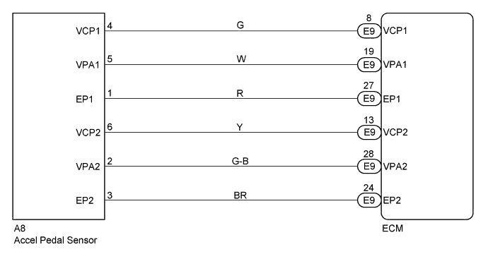
WIRING DIAGRAM
INSPECTION PROCEDURE
Tech Tips
-
Read freeze frame data using intelligent tester. Because freeze frame records the engine conditions when the malfunction is detected. When troubleshooting it is useful for determining whether the vehicle was running or stopped, the engine was warmed up or not, the air-fuel ratio was lean or rich, etc. at the time of the malfunction.
-
When not using the intelligent tester go to step 7.
PROCEDURE
-
READ VALUE OF INTELLIGENT TESTER (ACCELERATOR PEDAL OPENING PERCENTAGE)
-
Connect the intelligent tester to the DLC3.
-
Turn the ignition switch ON and push the intelligent tester main switch ON.
-
Read the accelerator pedal opening percentage.
Accelerator pedal Accelerator pedal opening position expressed as percentage Fully open 0 - 20 % Fully closed 80 - 100 %
OK 
CHECK FOR INTERMITTENT PROBLEMS Click here
NG 
-
-
CHECK ACCELERATOR LINK ASSEMBLY (CHECK VOLTAGE)
-
Disconnect the accelerator pedal position sensor connector.
-
Turn the ignition switch ON.
-
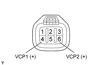
Check the voltage between terminals of the accelerator pedal position sensor connector as shown in the table and illustration.
Voltage Terminal
(Positive terminal ←→ Negative terminal)
Voltage VCP1 (4) ←→ Body ground 4.5 - 5.5 V VCP2 (6) ←→ Body ground
NG 
CHECK ECM (CHECK VOLTAGE) Click here
OK
-
-
CHECK ECM (CHECK VOLTAGE)
-
Turn the ignition switch ON.
-
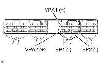
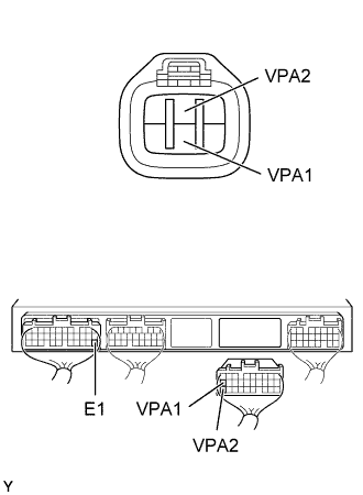
Check the voltage between terminals of the ECM connector as shown in the table and illustration.
Voltage Accelerator pedal Terminal
(Positive terminal ←→ Negative terminal)
Voltage Fully closed VPA1 (E9-19) ←→ EP1 (E9-27) 0.5 - 1.1 V VPA2 (E9-28) ←→ EP2 (E9-24) 0.9 - 2.3 V Fully open VPA1 (E9-19) ←→ EP1 (E9-27) 3.0 - 4.6 V VPA2 (E9-28) ←→ EP2 (E9-24) 3.4 - 5.0 V
OK
CHECK AND REPLACE ECM Click here
NG
-
-
CHECK WIRE HARNESS (ECM - ACCELERATOR PEDAL POSITION SENSOR)
-
Disconnect the accelerator pedal position sensor connector.
-
Disconnect the ECM (E9) connector.
-
Check the continuity between terminals of the accelerator pedal position sensor and ECM connectors as shown in the illustration and table.
Continuity (Check for open) Terminal
(Accelerator pedal position sensor ←→ ECM)
Standard VPA1 (5) ←→ VPA1 (E9-19) Continuity VPA2 (2) ←→ VPA2 (E9-28) Continuity (Check for short) Terminal
(ECM ←→ ECM(Ground))
Standard VPA1 (E9-19) ←→ E1 (E7-22) No continuity VPA2 (E9-28) ←→ E1 (E7-22)
OK
REPLACE ACCELERATOR LINK ASSEMBLY
NG 
REPAIR OR REPLACE HARNESS AND CONNECTOR
-
-
CHECK ECM (CHECK VOLTAGE)
-
Turn the ignition switch ON.
-
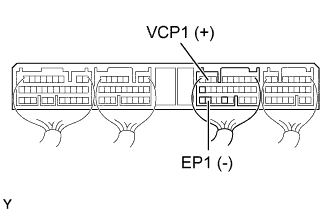
Check the voltage between terminals of the ECM connector as shown in the table and illustration.
Voltage Terminal
(Positive terminal ←→ Negative terminal)
Voltage VCP1 (E9-8) ←→ EP1 (E9-27) 4.5 - 5.5 V
NG
CHECK AND REPLACE ECM Click here
OK
-
-
CHECK WIRE HARNESS (ECM - ACCELERATOR PEDAL POSITION SENSOR)
-
Disconnect the accelerator pedal position sensor connector.
-
Disconnect the ECM (E9) connector.
-
Check the continuity between terminals of the accelerator pedal position sensor and ECM connectors as shown in the illustration and table.
Continuity (Check for open) Terminal
(Accelerator pedal position sensor ←→ ECM)
Standard VCP1 (4) ←→ VCP1 (E9-8) Continuity EP1 (1) ←→ EP1(E9-27) Continuity (Check for short) Terminal
(ECM ←→ ECM(Ground))
Standard VCP1 (E9-8) ←→ E1 (E7-22) No continuity EP1(E9-27) ←→ E1 (E7-22)
NG
REPAIR OR REPLACE HARNESS AND CONNECTOR
OK
CHECK AND REPLACE ECM Click here
-
-
CHECK ACCELERATOR LINK ASSEMBLY (CHECK VOLTAGE)
-
Disconnect the accelerator pedal position sensor connector.
-
Turn the ignition switch ON.
-
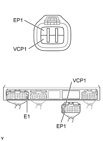
Check the voltage between terminals of the accelerator pedal position sensor connector as shown in the table and illustration.
Voltage Terminal
(Positive terminal ←→ Negative terminal)
Voltage VCP1 (4) ←→ Body ground 4.5 - 5.5 V VCP2 (6) ←→ Body ground
NG
CHECK ECM (CHECK VOLTAGE) Click here
OK
-
-
CHECK ECM (CHECK VOLTAGE)
-
Turn the ignition switch ON.
-
Check the voltage between terminals of the ECM connector as shown in the table and illustration.
Voltage Accelerator pedal Terminal
(Positive terminal ←→ Negative terminal)
Voltage Fully closed VPA1 (E9-19) ←→ EP1 (E9-27) 0.5 - 1.1 V VPA2 (E9-28) ←→ EP2 (E9-24) 0.9 - 2.3 V Fully open VPA1 (E9-19) ←→ EP1 (E9-27) 3.0 - 4.6 V VPA2 (E9-28) ←→ EP2 (E9-24) 3.4 - 5.0 V
OK
CHECK AND REPLACE ECM Click here
NG
-
-
CHECK WIRE HARNESS (ECM - ACCELERATOR PEDAL POSITION SENSOR)
-
Disconnect the accelerator pedal position sensor connector.
-
Disconnect the ECM (E9) connector.
-
Check the continuity between terminals of the accelerator pedal position sensor and ECM connectors as shown in the illustration and table.
Continuity (Check for open) Terminal
(Accelerator pedal position sensor ←→ ECM)
Standard VPA1 (5) ←→ VPA1 (E9-19) Continuity VPA2 (2) ←→ VPA2 (E9-28) Continuity (Check for short) Terminal
(ECM ←→ ECM(Ground))
Standard VPA1 (E9-19) ←→ E1 (E7-22) No continuity VPA2 (E9-28) ←→ E1 (E7-22)
NG
REPAIR OR REPLACE HARNESS AND CONNECTOR
OK
REPLACE ACCELERATOR LINK ASSEMBLY
-
-
CHECK ECM (CHECK VOLTAGE)
-
Turn the ignition switch ON.
-
Check the voltage between terminals of the ECM connector as shown in the table and illustration.
Voltage Terminal
(Positive terminal ←→ Negative terminal)
Voltage VCP1 (E9-8) ←→ EP1 (E9-27) 4.5 - 5.5 V
NG
CHECK AND REPLACE ECM Click here
OK
-
-
CHECK WIRE HARNESS (ECU - ACCELERATOR PEDAL POSITION SENSOR)
-
Disconnect the accelerator pedal position sensor connector.
-
Disconnect the ECM (E9) connector.
-
Check the continuity between terminals of the accelerator pedal position sensor and ECM connectors as shown in the illustration and table.
Continuity (Check for open) Terminal
(Accelerator pedal position sensor ←→ ECM)
Standard VCP1 (4) ←→ VCP1 (E9-8) Continuity EP1 (1) ←→ EP1(E9-27) Continuity (Check for short) Terminal
(ECM ←→ ECM(Ground))
Standard VCP1 (E9-8) ←→ E1 (E7-22) No continuity EP1(E9-27) ←→ E1 (E7-22)
NG
REPAIR OR REPLACE HARNESS AND CONNECTOR
OK
REPAIR OR REPLACE ECM
-