ECD SYSTEM, Diagnostic DTC:12
| DTC Code | DTC Name |
|---|---|
| 12 | Engine Speed Sensor Circuit Malfunction (TDC or G1 Circuit) |
DESCRIPTION
Camshaft position sensor (G1 signal) consists of a magnet, iron core and pickup coil.
The G1 signal plate has 5 teeth on its outer circumference and is installed the pump drive shaft pulley. When the pump drive shaft pulley rotate, the protrusion on the signal plate and the air gap on the pickup coil change, causing fluctuations in the magnetic field and generating an electromotive force in the pickup coil. The NE signal plate has 34 teeth and is mounted on the crank angle sensor plate. The NE signal sensor generates 34 signals at every engine revolution. The ECM detects the standard crankshaft angle based on the G1 signal and the actual crankshaft angle and the engine speed by the NE signal.
| DTC No. | DTC Detecting Condition | Trouble Area |
| 12 | No camshaft position sensor signal to ECU during cranking |
|
| No camshaft position sensor signal to ECU with engine speed 650 rpm or more |
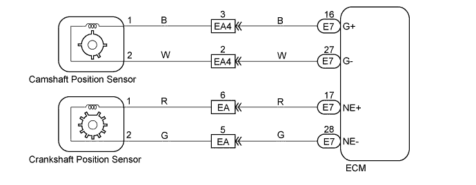
WIRING DIAGRAM
INSPECTION PROCEDURE
Tech Tips
-
Perform troubleshooting of DTC 12 first. If no trouble is found, troubleshoot the following mechanical system.
-
Read freeze frame data using intelligent tester. Because freeze frame records the engine conditions when the malfunction is detected. When troubleshooting it is useful for determining whether the vehicle was running or stopped, the engine was warmed up or not, the air-fuel ratio was lean or rich, etc. at the time of the malfunction.
PROCEDURE
-
CHECK CAMSHAFT POSITION SENSOR
-
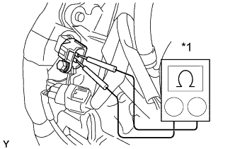
Text in Illustration *1 Ohmmeter Check the resistance between terminals of the camshaft position sensor.
Resistance Cold 1630 - 2740 Ω Hot 2065 - 3225 Ω Tech Tips
"Cold" and "Hot" above express the temperature of the part itself. "Cold" is from -10°C (14°F) to 50°C (122°F) and "Hot" is from 50°C (122°F) to 100°C (212°F).
-
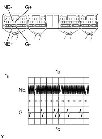
Text in Illustration *a 5 V/ Division *b G and NE Signal Waveforms *c 20 msec./Division (Idling) Reference:
Inspection using the oscilloscope.
-
During cranking or idling, check the waveform between terminals G+ and G-, and NE+ and NE- of the ECM connector.
Tech Tips
The correct waveforms are as shown in the left.
-
NG 
REPLACE CAMSHAFT POSITION SENSOR
OK 
-
-
CHECK WIRE HARNESS (ECM - CAMSHAFT POSITION SENSOR)
-
Disconnect the camshaft position sensor connector.
-
Disconnect the ECM (E7) connector.
-
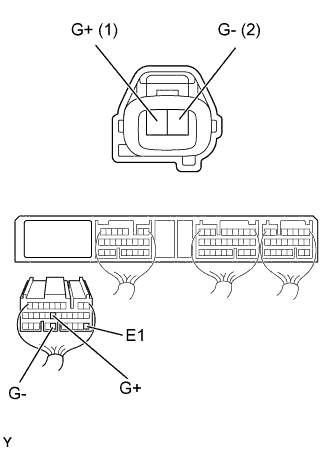
Check the continuity between terminals of the camshaft position sensor and ECM connectors as shown in the illustration and table.
Continuity (Check for open) Terminal
(Camshaft position sensor ←→ ECM)
Standard G+ (1) ←→ G+ (E7-16) Continuity G- (2) ←→ G- (E7-27) Continuity (Check for short) Terminal
(ECM ←→ ECM(Ground))
Standard G+ (E7-16) ←→ E1 (E7-22) No continuity G- (E7-27) ←→ E1 (E7-22)
NG
REPAIR OR REPLACE HARNESS AND CONNECTOR
OK
-
-
CHECK SENSOR ATTACHMENT PART
-
Inspect the camshaft position sensor installation.
NG
REPAIR OR REPLACE SENSOR ATTACHMENT PART
OK
-
-
INSPECT PUMP DRIVE SHAFT PULLEY (TEETH OF SIGNAL PLATE)
-
Remove the pump drive shaft pulley Click here.
-
Check the teeth of signal plate.
MG
REPLACE PUMP DRIVE SHAFT PULLEY
OK 
CHECK AND REPLACE ECM Click here
-