CYLINDER HEAD (w/o DPF) INSTALLATION

-
INSTALL CYLINDER HEAD GASKET
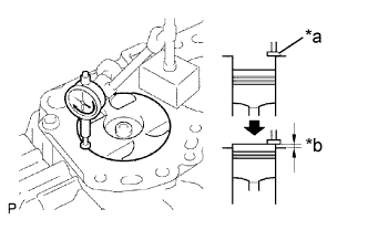
Text in Illustration *a Measuring Tip *b Protrusion
-
Find where the piston head protrudes most by slowly turning the crankshaft clockwise and counterclockwise.
-
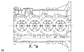
Text in Illustration *a Measuring Point Measure the piston protrusion of each cylinder at 2 points as shown in the illustration.
-
For the piston protrusion value of each cylinder, use the average of the 2 measurements of each cylinder.
Standard piston protrusion 0.005 to 0.254 mm (0.0002 to 0.0100 in.) Tech Tips
If the protrusion is not as specified, remove the piston and connecting rod assembly and reinstall them.
-
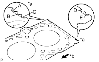
Text in Illustration *a Cutout Mark *b Front Select a new cylinder head gasket.
Tech Tips
New cylinder head gaskets are available in 5 sizes, and are marked A, B, C, D or E.
New installed cylinder head gasket thickness Mark Thickness A 0.80 to 0.90 mm (0.0315 to 0.0354 in.) B 0.85 to 0.95 mm (0.0335 to 0.0374 in.) C 0.90 to 1.00 mm (0.0354 to 0.0394 in.) D 0.95 to 1.05 mm (0.0374 to 0.0413 in.) E 1.00 to 1.10 mm (0.0394 to 0.0433 in.)
-
Select the largest piston protrusion value from the measurements made. Then select a new appropriate gasket according to the table below.
Use gasket size Gasket Size Piston Protrusion Use A 0.005 to 0.054 mm (0.0002 to 0.0021 in.) Use B 0.055 to 0.104 mm (0.0022 to 0.0041 in.) Use C 0.105 to 0.154 mm (0.0041 to 0.0061 in.) Use D 0.155 to 0.204 mm (0.0061 to 0.0080 in.) Use E 0.205 to 0.255 mm (0.0081 to 0.0100 in.)
-
-
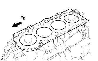
Text in Illustration *a Front Place the cylinder head on the cylinder block.
-
Place the cylinder head gasket on the cylinder block.
Note
Be careful of the installation direction.
-
Place the cylinder head on the cylinder head gasket.
-
-
-
INSTALL CYLINDER HEAD SUB-ASSEMBLY
Tech Tips
-
The cylinder head bolts are tightened in 3 progressive steps.
-
If any bolt is broken or deformed, replace it.
-
Apply a light coat of engine oil to the threads and under the heads of the cylinder head bolts.
-
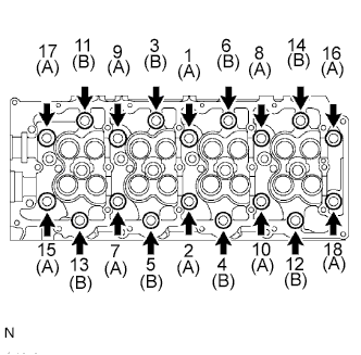
Install and uniformly tighten the 18 cylinder head bolts and 18 washers, in several passes in the sequence shown in the illustration.
- Torque:
- 85 N*m { 867 kgf*cm, 63 ft.*lbf }
Bolt Length A 110 mm (4.33 in.) B 167 mm (6.57 in.) If any of the cylinder head bolts does not meet the torque specification, replace it.
-
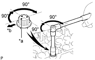
Text in Illustration *a Painted Mark *b Front Mark the front of the cylinder head bolts with paint.
-
Further tighten the cylinder head bolts by 90° in the sequence shown in the illustration above.
-
Finally, tighten the cylinder head bolts by an additional 90°.
-
Check that the painted mark is now facing rearward.
-
-
INSTALL CAMSHAFTS
-
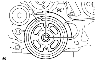
Using the crankshaft pulley bolt, set the No. 1 cylinder to 90° BTDC/compression.
Tech Tips
Set the No. 1 cylinder to 90° BTDC/compression to avoid interference with the piston top and valve head.
-
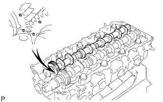
Install the camshaft.
-
Apply MP grease to the thrust portion of the camshaft.
-
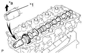
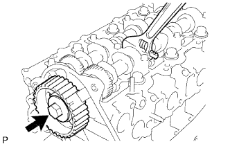
Place the camshaft on the cylinder head, facing the key groove upward.
Text in Illustration *1 Key Groove *a Upward -
Align the timing marks (1 dot mark) of the camshaft drive and driven main gears, and set the No. 2 camshaft in place.
-
-
Remove any old packing (FIPG) material from the camshaft bearing cap.
-
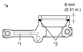
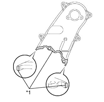
Apply seal packing to the specified areas shown in the illustration.
Text in Illustration *1 Oil Passage *2 Seal Packing *a Seal Diameter: 4 mm Seal packing Toyota Genuine Seal Packing Black, Three Bond 1207B or equivalent Standard seal diameter 4 mm (0.16 in.) Note
-
Do not allow FIPG to come into contact with the oil passage of the bearing cap.
-
After applying FIPG, install the camshaft bearing caps within 3 minutes and tighten the bolts within 15 minutes.
-
Do not start the engine for at least 2 hours after the installation.
-
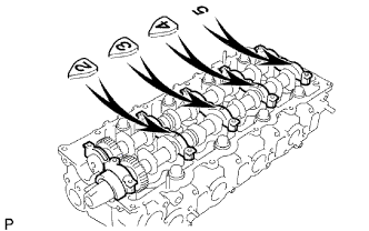
Install the 5 bearing caps in the proper locations.
-
Apply a light coat of engine oil to the threads and under the heads of the bearing cap bolts.
-
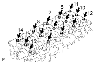
Install and uniformly tighten the 15 bearing cap bolts in several passes in the sequence shown in the illustration.
- Torque:
- 19 N*m { 194 kgf*cm, 14 ft.*lbf }
-
-
-
INSTALL CAMSHAFT SETTING OIL SEAL
-
Apply MP grease to the lip of a new oil seal.
-
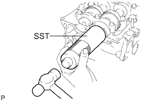
Using SST and a hammer, tap in the oil seal until its surface is flush with the oil seal retainer edge.
- SST
- 09608-06041
-
-
INSPECT VALVE CLEARANCE
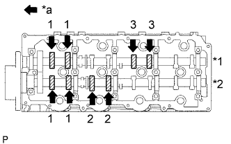
Text in Illustration *1 Exhaust *2 Intake *a Front
-
Check only the valves indicated.
-
Using a feeler gauge, measure the clearance between the valve lifter and camshaft.
Standard valve clearance (Cold) Intake Exhaust 0.20 to 0.30 mm (0.008 to 0.012 in.) 0.35 to 0.45 mm (0.014 to 0.018 in.) Write down the valve clearance measurements that are not within the specified range. These measurements will be used later to determine the size of the adjustment shim to be installed.
-
-
Turn the crankshaft 360° to set the No. 4 cylinder to TDC / compression.
-
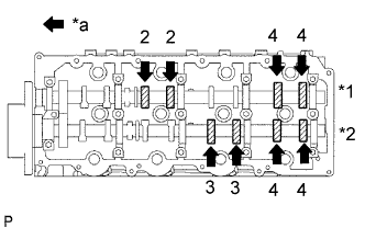
Text in Illustration *1 Exhaust *2 Intake *a Front Check only the valves indicated.
-
Using a feeler gauge, measure the clearance between the valve lifter and camshaft.
Standard valve clearance Intake Exhaust 0.20 to 0.30 mm (0.008 to 0.012 in.) 0.35 to 0.45 mm (0.014 to 0.018 in.) Write down the valve clearance measurements that are not within the specified range. These measurements will be used later to determine the size of the adjustment shim to be installed.
-
-
-
ADJUST VALVE CLEARANCE
-
Remove the camshafts Click here.
-
Remove the 8 valve lifters.
-
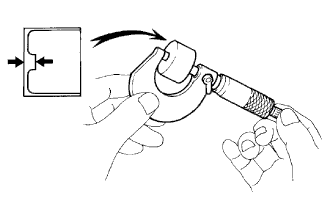
Using a micrometer, measure the thickness of the removed lifter.
-
Calculate the thickness of a new lifter so that the valve clearance comes within the specified value.
A B C New lifter thickness Used lifter thickness Measured valve clearance New lifter thickness Intake A = B + (C - 0.25 mm (0.0098 in.)) Exhaust A = B + (C - 0.40 mm (0.00158 in.)) -
Select a new lifter with a thickness as close as possible to the calculated values.
Tech Tips
Valve lifters are available in 35 sizes in increments of 0.020 mm (0.0008 in.), from 5.060 mm (0.1992 in.) to 5.740 mm (0.2260 in.).
-
Install the selected valve lifter.
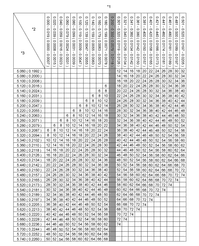
Text in Illustration *1 Intake Valve Lifter Chart (1/2) *2 Measured Clearance mm (in.) *3 Installed Lifter Thickness mm (in.) - - 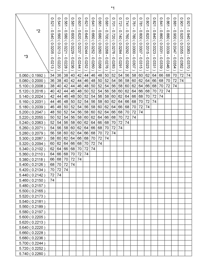
Text in Illustration *1 Intake Valve Lifter Chart (2/2) *2 Measured Clearance mm (in.) *3 Installed Lifter Thickness mm (in.) - - Standard intake valve clearance (Cold) 0.20 to 0.30 mm (0.008 to 0.012 in.) EXAMPLE The 5.250 mm (0.2067 in.) lifter is installed, and the measured clearance is 0.400 mm (0.0158 in.). Replace the 5.250 mm (0.2067 in.) shim with a No. 40 lifter. New lifter thickness (mm (in.)) Shim No. Thickness Shim No. Thickness Shim No. Thickness 06 5.060 (0.1992) 30 5.300 (0.2087) 54 5.540 (0.2181) 08 5.080 (0.2000) 32 5.320 (0.2094) 56 5.560 (0.2189) 10 5.100 (0.2008) 34 5.340 (0.2102) 58 5.580 (0.2197) 12 5.120 (0.2016) 36 5.360 (0.2110) 60 5.600 (0.2205) 14 5.140 (0.2024) 38 5.380 (0.2118) 62 5.620 (0.2213) 16 5.160 (0.2031) 40 5.400 (0.2126) 64 5.640 (0.2220) 18 5.180 (0.2039) 42 5.420 (0.2134) 66 5.660 (0.2228) 20 5.200 (0.2047) 44 5.440 (0.2142) 68 5.680 (0.2236) 22 5.220 (0.2055) 46 5.460 (0.2150) 70 5.700 (0.2244) 24 5.240 (0.2063) 48 5.480 (0.2157) 72 5.720 (0.2252) 26 5.260 (0.2071) 50 5.500 (0.2165) 74 5.740 (0.2260) 28 5.280 (0.2079) 52 5.520 (0.2173) - - 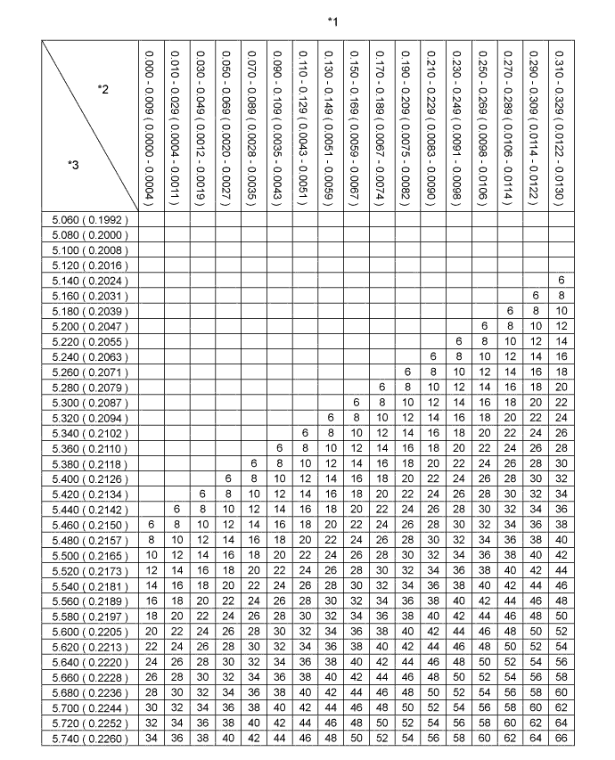
Text in Illustration *1 Exhaust Valve Lifter Chart (1/3) *2 Measured Clearance mm (in.) *3 Installed Lifter Thickness mm (in.) - - 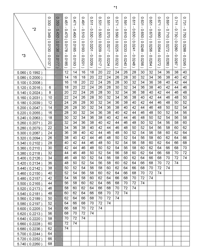
Text in Illustration *1 Exhaust Valve Lifter Chart (2/3) *2 Measured Clearance mm (in.) *3 Installed Lifter Thickness mm (in.) - - 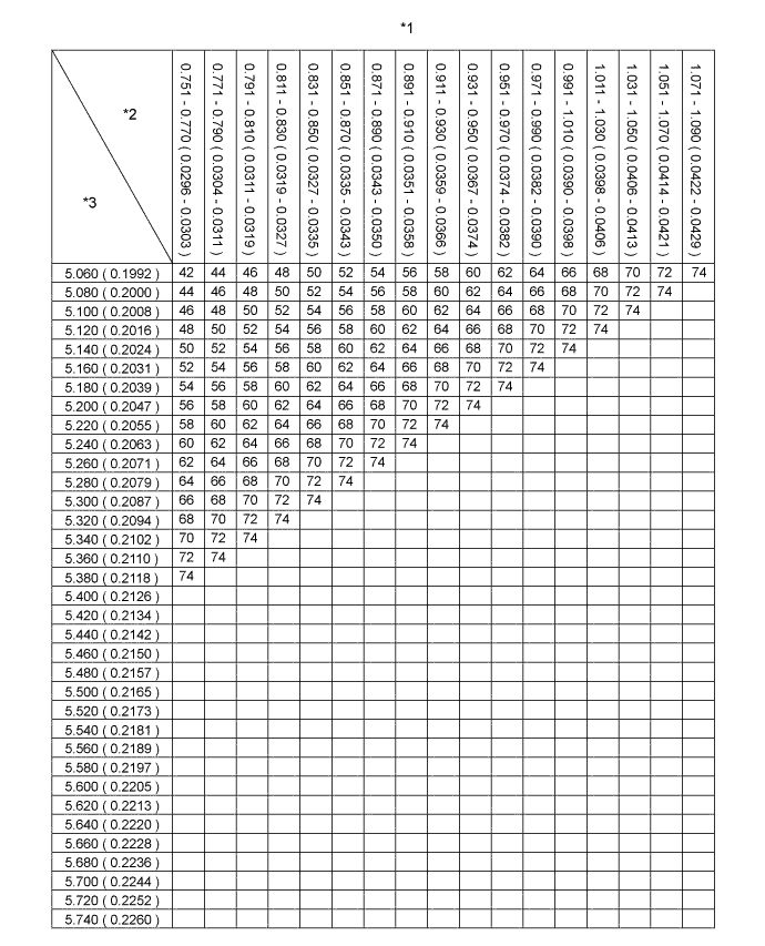
Text in Illustration *1 Exhaust Valve Lifter Chart (3/3) *2 Measured Clearance mm (in.) *3 Installed Lifter Thickness mm (in.) - - Standard exhaust valve clearance (Cold) 0.35 to 0.45 mm (0.014 to 0.018 in.) EXAMPLE The 5.340 mm (0.2102 in.) lifter is installed, and the measured clearance is 0.480 mm (0.0189 in.). Replace the 5.340 mm (0.2102 in.) shim with a No. 42 lifter. New lifter thickness (mm (in.)) Shim No. Thickness Shim No. Thickness Shim No. Thickness 06 5.060 (0.1992) 30 5.300 (0.2087) 54 5.540 (0.2181) 08 5.080 (0.2000) 32 5.320 (0.2094) 56 5.560 (0.2189) 10 5.100 (0.2008) 34 5.340 (0.2102) 58 5.580 (0.2197) 12 5.120 (0.2016) 36 5.360 (0.2110) 60 5.600 (0.2205) 14 5.140 (0.2024) 38 5.380 (0.2118) 62 5.620 (0.2213) 16 5.160 (0.2031) 40 5.400 (0.2126) 64 5.640 (0.2220) 18 5.180 (0.2039) 42 5.420 (0.2134) 66 5.660 (0.2228) 20 5.200 (0.2047) 44 5.440 (0.2142) 68 5.680 (0.2236) 22 5.220 (0.2055) 46 5.460 (0.2150) 70 5.700 (0.2244) 24 5.240 (0.2063) 48 5.480 (0.2157) 72 5.720 (0.2252) 26 5.260 (0.2071) 50 5.500 (0.2165) 74 5.740 (0.2260) 28 5.280 (0.2079) 52 5.520 (0.2173) - - -
Install the camshaft Click here.
-
-
INSTALL CYLINDER BLOCK INSULATOR
-
INSTALL NO. 2 TIMING BELT COVER
Text in Illustration *1 Seal Packing
-
Apply seal packing (FIPG) to the specified areas shown in the illustration.
Seal packing Toyota Genuine Seal Packing Black, Three Bond 1207B or equivalent. Note
After applying FIPG, install the No. 2 timing belt cover within 3 minutes and tighten the bolts and nut within 15 minutes.
-
Install the No. 2 timing belt cover with the 4 bolts and nut.
- Torque:
- 10 N*m { 102 kgf*cm, 7 ft.*lbf }
-
-
INSTALL CAMSHAFT TIMING PULLEY
-
Install the camshaft timing pulley.
-
Fasten the bolt of the camshaft timing pulley while holding the camshaft with a wrench.
- Torque:
- 98 N*m { 1000 kgf*cm, 72 ft.*lbf }
-
-
INSTALL EXHAUST MANIFOLD
-
Install the new gasket onto the cylinder head.
-
Install the exhaust manifold with the 8 nuts, spacers and collars.
- Torque:
- 40 N*m { 408 kgf*cm, 30 ft.*lbf }
Note
Make sure that the side of the collar with the smaller diameter faces the exhaust manifold.
-
-
TEMPORARILY TIGHTEN TURBO OIL INLET PIPE SUB-ASSEMBLY
-
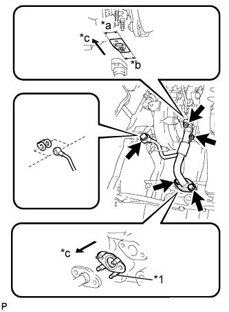
Text in Illustration *1 Claw *a Wide *b Narrow *c Outside Install a new gasket to the turbo oil inlet pipe sub-assembly.
Note
Insert the gasket with its claws facing the turbo oil inlet pipe sub-assembly.
-
Temporarily tighten the turbo oil inlet pipe sub-assembly with the 2 bolts, 2 nuts and union bolt.
-
-
TEMPORARILY TIGHTEN TURBOCHARGER STAY
-
Temporarily tighten the turbocharger stay with the 2 bolts and a new nut.
-
-
FULLY TIGHTEN TURBOCHARGER STAY
-
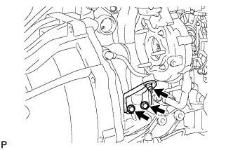
Tighten the 2 bolts and nut to the specified torque.
- Torque:
- 24 N*m { 245 kgf*cm, 18 ft.*lbf }
-
-
FULLY TIGHTEN TURBO OIL INLET PIPE SUB-ASSEMBLY
-
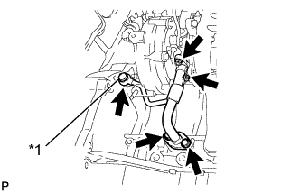
Text in Illustration *1 Union Bolt Tighten the 2 bolts, 2 nuts and union bolt to the specified torque and install the turbo oil inlet sub-assembly.
- Torque:
- 12 N*m { 122 kgf*cm, 9 ft.*lbf, for bolt }
- 13 N*m { 133 kgf*cm, 10 ft.*lbf, for nut }
- 26 N*m { 265 kgf*cm, 19 ft.*lbf, for union bolt }
-
-
INSTALL TURBINE OUTLET ELBOW
-
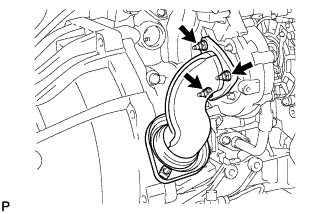
Install a new gasket and the turbine outlet elbow with the new 3 nuts.
- Torque:
- 26 N*m { 260 kgf*cm, 19 ft.*lbf }
-
-
CONNECT NO. 1 TURBO WATER HOSE
-
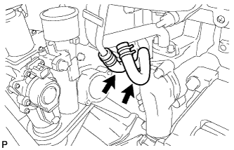
Connect the No. 1 turbo water hose with the 2 clips.
-
-
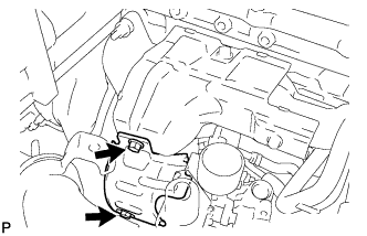
INSTALL NO. 1 EXHAUST MANIFOLD HEAT INSULATOR
-
Temporarily install the No. 1 exhaust manifold heat insulator with the 2 bolts.
-
-
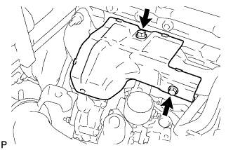
INSTALL NO. 1 TURBO INSULATOR
-
Temporarily install the No. 1 turbo insulator with the 2 bolts.
-
Tighten the 4 bolts to the specified torque and install the No. 2 turbo insulator and No. 1 exhaust manifold heat insulator.
- Torque:
- 12 N*m { 122 kgf*cm, 9 in.*lbf }
-
-
INSTALL VENTILATION PIPE SUB-ASSEMBLY
-
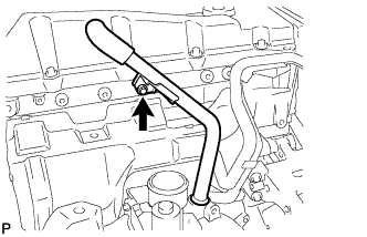
Install a new O-ring to the ventilation pipe sub-assembly.
-
Apply a small amount of engine oil to the O-ring and install it to the ventilation pipe sub-assembly with the bolt.
- Torque:
- 20 N*m { 204 kgf*cm, 15 ft.*lbf }
-
-
INSTALL ENGINE WIRE HARNESS (for LHD)
-
Install the engine wire harness with bracket with the 2 bolts.
- Torque:
- 8.0 N*m { 82 kgf*cm, 71 in.*lbf }
-
-
INSTALL ENGINE WIRE HARNESS (for RHD)
-
Install the engine wire harness with bracket with the 2 bolts.
- Torque:
- 8.0 N*m { 82 kgf*cm, 71 in.*lbf }
-
-
CONNECT TURBOCHARGER STROKE SENSOR CONNECTOR
-
Connect the turbocharger stroke sensor connector to the turbocharger.
-
-
INSTALL NO. 2 AIR CLEANER HOSE
-
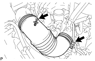
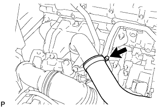
Connect the No. 2 air hose and tighten the hose clamp.
- Torque:
- 4.0 N*m { 41 kgf*cm, 35 in.*lbf }
-
-
CONNECT TURBOCHARGER MOTOR CONNECTOR
-
Connect the turbocharger motor connector to the turbocharger.
-
-
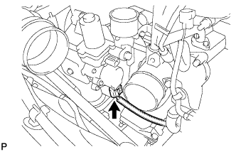
INSTALL COMPRESSOR OUTLET ELBOW
-
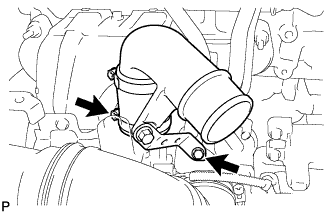
Install the compressor outlet elbow with No. 2 air hose with the hose clamp and bolt.
- Torque:
- 20 N*m { 204 kgf*cm, 15 ft.*lbf, for bolt }
- 6.5 N*m { 66 kgf*cm, 58 in.*lbf, for hose clamp }
-
-
CONNECT NO. 1 AIR HOSE
-
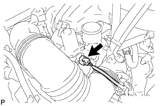
Connect the No. 1 air hose and tighten the hose clamp.
-
-
INSTALL FRONT EXHAUST PIPE ASSEMBLY
-
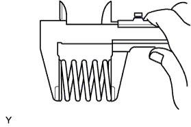
Inspect the compression spring.
-
Using vernier calipers, measure the free length of the compression spring.
Minimum length 40.5 mm (1.594 in.) If the free length is less than the minimum, replace the compression spring.
-
-
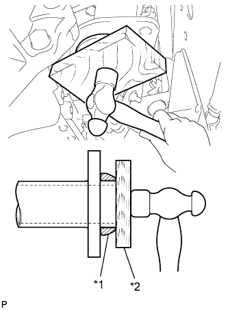
Text in Illustration *1 New Gasket *2 Wooden Block Install a new gasket.
-
Using a wooden block and plastic-faced hammer, tap in a new gasket until its flush with the front exhaust pipe end.
Note
-
Install the gasket in the correct direction.
-
Do not damage the outer surface of the gasket.
-
Do not reuse the removed gasket.
-
Do not push in the gasket with the front exhaust pipe when connecting it.
-
-
-
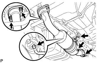
Install the 2 hooks and the front exhaust pipe.
-
Install the front exhaust pipe with the 2 bolts and compression springs onto the exhaust manifold.
- Torque:
- 43 N*m { 438 kgf*cm, 32 ft.*lbf }
-
Install the gasket onto the front exhaust pipe.
-
Install the front exhaust pipe with the 2 bolts onto the center exhaust pipe.
- Torque:
- 43 N*m { 438 kgf*cm, 32 ft.*lbf }
-
-
INSTALL OIL LEVEL GAUGE GUIDE (for LHD)
-
Install the a O-ring onto the oil level gauge guide.
-
Install the oil level gauge guide with the bolt.
- Torque:
- 8.0 N*m { 82 kgf*cm, 71 in.*lbf }
-
Install the oil level gauge.
-
-
INSTALL INTAKE MANIFOLD
-
Install a new gasket.
-
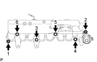
Temporarily install the intake manifold with the 2 nuts and the 4 bolts.
-
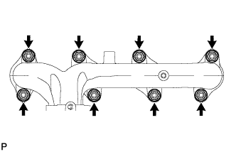
Uniformly tighten the 2 nuts and the 4 bolts as shown in the illustration.
- Torque:
- 29 N*m { 296 kgf*cm, 21 ft.*lbf }
-
-
INSTALL FUEL COOLER
-
Install the fuel cooler with the 2 bolts.
- Torque:
- 20 N*m { 204 kgf*cm, 15 ft.*lbf }
-
-
INSTALL NO. 1 INTAKE MANIFOLD INSULATOR
-
INSTALL GLOW PLUG ASSEMBLY
Note
-
Measure the resistance of the glow plug when reinstalling it.
If the result is not as specified, replace it with a new one.
-
Replace the glow plug with a new one when it has been dropped or subjected to a physical impact.
-
Remove any carbon deposits from the glow plug hole when reinstalling it.
-
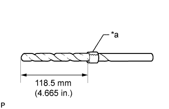
Text in Illustration *a Tape Wrap tape around a φ 4.4 drill, 118.5 mm (4.665 in.) from its tip.
-
Insert the drill 118.5 mm (4.665 in.) into the glow plug hole and remove the carbon deposits by manually turning the drill.
-
Insert the φ 4 drill into the glow plug hole and remove any carbon deposits from the tip end portion of the glow plug hole by manually turning the drill.
-
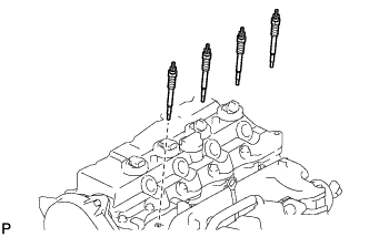
Install the 4 glow plugs.
- Torque:
- 13 N*m { 133 kgf*cm, 10 ft.*lbf }
Note
Do not use any tools, such as air tools, which are liable to cause any impact to the glow plugs, when installing them.
-
-
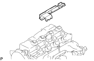
INSTALL NO. 2 INTAKE MANIFOLD INSULATOR
-
Install the No. 2 Intake manifold Insulator.
-
-
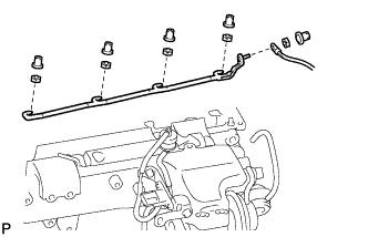
INSTALL NO. 1 GLOW PLUG CONNECTOR
-
Temporarily install the No. 1 glow plug connector with the 4 nuts.
-
Tighten the 4 nuts to the specified torque.
- Torque:
- 2.2 N*m { 22 kgf*cm, 19 in.*lbf }
-
Install the 4 screw grommets.
-
Connect the wire harness to the No. 1 glow plug connector and install the nut.
- Torque:
- 2.6 N*m { 27 kgf*cm, 23 in.*lbf }
-
Install the screw grommet.
-
-
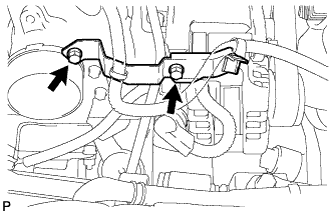
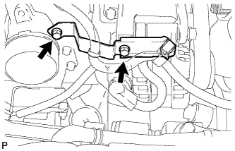
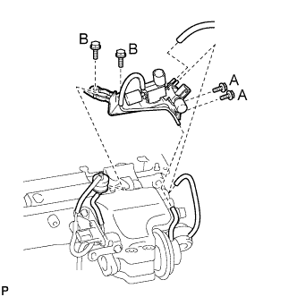
INSTALL MANIFOLD STAY
-
Install the manifold stay with the 4 bolts.
- Torque:
- 8.0 N*m { 82 kgf*cm, 71 in.*lbf, for bolt A }
- 19 N*m { 194 kgf*cm, 14 ft.*lbf, for bolt B }
-
Connect the 3 vacuum hoses and gas filter.
-
-
INSTALL COMMON RAIL ASSEMBLY
-
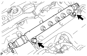
Install the common rail with the 2 bolts.
- Torque:
- 38 N*m { 387 kgf*cm, 28 ft.*lbf }
-
Connect the fuel hose.
-
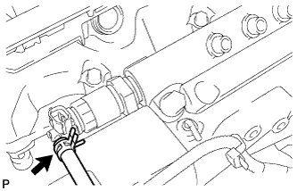
Connect the 2 connectors to the common rail.
-
-
INSTALL INJECTOR ASSEMBLY
Refer to the procedures up to "INSTALL INJECTOR ASSEMBLY" Click here.
-
INSTALL TIMING BELT
Refer to the procedures up to "INSTALL TIMING BELT" Click here.
-
ADD ENGINE OIL
-
Add fresh oil and install the oil filler cap.
Engine oil Oil Grade Oil Viscosity (SAE)
-
API CF-4 or CF, G-DLD-1, ACEA B1
-
20W-50
-
15W-40
-
10W-30
-
5W-30 Preferred
Capacity Item Fill Amount Drain and refill with oil filter change 7.0 liters (7.4 US qts, 6.2 lmp. qts) Drain and refill without oil filter change 6.8 liters (7.2 US qts, 6.0 lmp. qts) Dry fill 7.7 liters (8.1 US qts, 6.8 lmp. qts) -
-
-
INSPECT FOR ENGINE OIL LEAK
-
INSPECT FOR OIL LEVEL
-
Warm up the engine and inspect for oil leak.
-