CYLINDER HEAD (w/o DPF) INSPECTION
-
CLEAN CYLINDER HEAD SUB-ASSEMBLY
-
Clean the cylinder head.
-
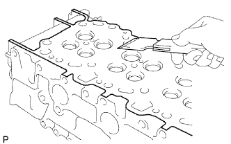
Using a gasket scraper, remove all the gasket material from the cylinder block contact surface.
Note
Be careful not to scratch the cylinder block contact surface.
-
-
Using a valve guide bushing brush and solvent, clean all the guide bushes.
-
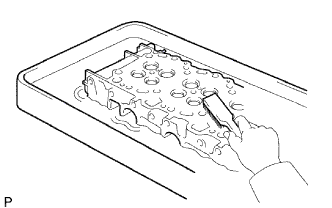
Using a soft brush and solvent, thoroughly clean the cylinder head.
-
-
INSPECT CYLINDER HEAD SUB-ASSEMBLY
-
Inspect the cylinder head warpage.
-
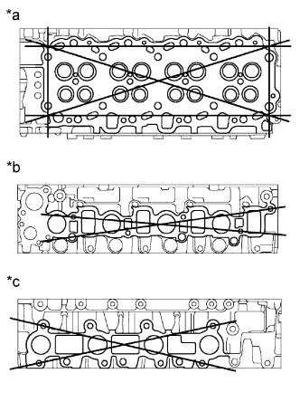
Using a precision straightedge and feeler gauge, measure the surfaces, which contact the cylinder block and the manifolds, for warpage.
Text in Illustration *a Cylinder Block Side *b Intake Manifold Side *c Exhaust Manifold Side Maximum warpage 0.15 mm (0.005 in.) If the warpage is greater than the maximum, replace the cylinder head.
-
-
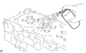
Inspect the cylinder head for cracks.
-
Using a dye penetrant, check the combustion chamber, intake ports, exhaust ports and cylinder block surface for cracks.
If cracked, replace the cylinder head.
-
-
-
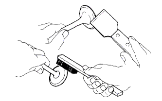
CLEAN INTAKE VALVE
-
Using a gasket scraper, chip off any carbon from the valve head.
-
Using a wire brush, thoroughly clean the valve.
-
-
INSPECT INTAKE VALVE
-
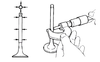
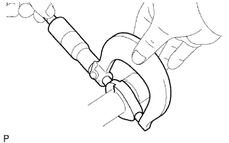
Using a micrometer, measure the diameter of the valve stem.
Standard valve stem diameter 5.970 to 5.985 mm (0.2350 to 0.2356 in.) If the diameter is not as specified, replace the valve.
-
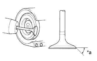
Text in Illustration *a Valve Face Angle Check the valve face angle.
-
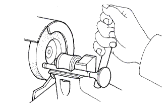
Grind the valve enough to remove pits and carbon.
-
Check that the valve is ground to the correct valve face angle.
Standard valve face angle 44.5° If the valve is worn, replace the valve.
-
-
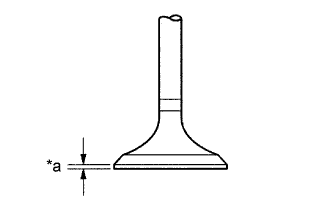
Text in Illustration *a Margin Thickness Check the valve head margin thickness.
Standard margin thickness 1.1 mm (0.043 in.) Minimum margin thickness 0.8 mm (0.032 in.) If the margin thickness is less than the minimum, replace the valve.
-
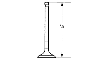
Text in Illustration *a Overall Length Check the valve overall length.
Standard overall length 105.15 to 105.75 mm (4.1398 to 4.1634 in.) Minimum overall length 104.65 mm (4.1201 in.) If the overall length is less than the minimum, replace the valve.
-
Check the surface of the valve stem tip for wear.
If the valve stem tip is worn, resurface the tip with a grinder or replace the valve.
Note
Do not grind off more than the minimum.
-
-
CLEAN EXHAUST VALVE
-
Using a gasket scraper, chip off any carbon from the valve head.
-
Using a wire brush, thoroughly clean the valve.
-
-
INSPECT EXHAUST VALVE
-
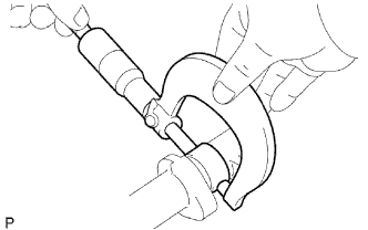
Using a micrometer, measure the diameter of the valve stem.
Standard valve stem diameter 5.960 to 5.975 mm (0.2346 to 0.2352 in.) If the diameter is not as specified, replace the valve.
-
Text in Illustration *a Valve Face Angle Check the valve face angle.
-
Grind the valve enough to remove pits and carbon.
-
Check that the valve is ground to the correct valve face angle.
Standard valve face angle 44.5° If the valve face is worn, replace the valve.
-
-
Text in Illustration *a Margin Thickness Check the valve head margin thickness.
Standard margin thickness 1.2 mm (0.047 in.) Minimum margin thickness 0.7 mm (0.028 in.) If the margin thickness is less than the minimum, replace the valve.
-
Text in Illustration *a Overall Length Check the valve overall length.
Standard overall length 105.02 to 105.62 mm (4.1347 to 4.1583 in.) Minimum overall length 104.52 mm (4.1150 in.) If the overall length is less than the minimum, replace the valve.
-
Check the surface of the valve stem tip for wear.
If the valve stem tip is worn, resurface the tip with a grinder or replace the valve.
Note
Do not grind off more than the minimum.
-
-
INSPECT INNER COMPRESSION SPRING
-
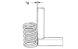
Using a steel square, measure the deviation of the inner compression spring.
Text in Illustration *a Deviation Maximum deviation 2.0 mm (0.079 in.) If the deviation is greater than the maximum, replace the inner compression spring.
-
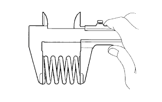
Using vernier calipers, measure the free length of the spring.
Standard free length 46.5 mm (1.831 in.) If the free length is not as specified, replace the spring.
-
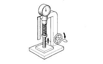
Using a spring tester, measure the tension of the valve spring at the specified installed length.
Standard installed tension (at 33.1 mm (1.303 in.)) 150.2 to 165.8 N (15.3 to 16.9 kgf, 33.7 to 37.3 lbf) If the tension is not as specified, replace the spring.
-
-
INSPECT INTAKE VALVE GUIDE BUSH
-
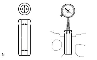
Using a caliper gauge, measure the inside diameter of the guide bush.
Standard bush inside diameter 6.01 to 6.03 mm (0.2366 to 0.2374 in.) If the journal diameter is not as specified, check the oil clearance.
-
Subtract the valve stem diameter measurement from the guide bush inside diameter measurement.
Standard oil clearance 0.025 to 0.060 mm (0.0010 to 0.0024 in.) Maximum oil clearance 0.08 mm (0.0032 in.) If the clearance is greater than the maximum, replace the intake valve and guide bush.
-
-
INSPECT EXHAUST VALVE GUIDE BUSH
-
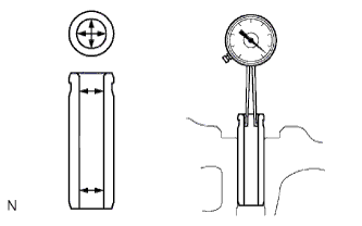
Using a caliper gauge, measure the inside diameter of the guide bush.
Standard bush inside diameter 6.01 to 6.03 mm (0.2366 to 0.2374 in.) If the journal diameter is not as specified, check the oil clearance.
-
Subtract the valve stem diameter measurement from the guide bush inside diameter measurement.
Standard oil clearance 0.035 to 0.070 mm (0.0014 to 0.0028 in.) Maximum oil clearance 0.10 mm (0.0039 in.) If the clearance is greater than the maximum, replace the exhaust valve and guide bush.
-
-
INSPECT INTAKE VALVE SEAT
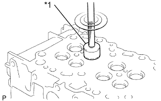
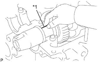
Text in Illustration *1 45° Carbide Cutter
-
Using a 45° carbide cutter, resurface the valve seats. Remove only enough metal to clean the seats.
-
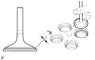
Text in Illustration *a Width Check the valve seating position.
-
Apply a light coat of Prussian blue to the valve face.
-
Lightly press the valve against the seat. Do not rotate the valve.
-
-
Check the valve face and seat for the following:
-
If blue appears 360° around the face, the valve is concentric. If not, replace the valve.
-
If blue appears 360° around the valve seat, the guide and face are concentric. If not, resurface the seat.
-
Check that the seat contact is in the middle of the valve face with the width below.
Standard width 1.2 to 1.6 mm (0.047 to 0.063 in.)
-
-
-
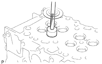
INSPECT EXHAUST VALVE SEAT
-
Using a 45° carbide cutter, resurface the valve seats. Remove only enough metal to clean the seats.
-
Check the valve seating position.
-
Apply a light coat of Prussian blue to the valve face.
-
Lightly press the valve against the seat. Do not rotate valve.
-
-
Check the valve face and seat for the following:
-
If blue appears 360° around the face, the valve is concentric. If not, replace the valve.
-
If blue appears 360° around the valve seat, the guide and face are concentric. If not, resurface the seat.
-
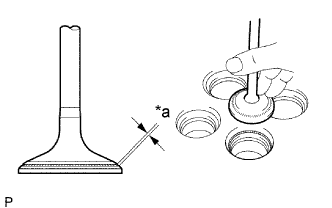
Check that the seat contact is in the middle of the valve face with the width below.
Text in Illustration *a Width Standard width 1.6 to 2.0 mm (0.063 to 0.079 in.)
-
-
-
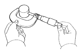
INSPECT VALVE LIFTER
-
Using a micrometer, measure the lifter diameter.
Standard lifter diameter 30.966 to 30.976 mm (1.2191 to 1.2195 in.) -
Using a caliper gauge, measure the lifter bore diameter of the cylinder head.
Standard lifter bore diameter 31.000 to 31.021 mm (1.2205 to 1.2213 in.) If the lifter diameter is not as specified, check the oil clearance.
-
Measure the oil clearance by subtracting the lifter diameter measurement from the lifter bore diameter measurement.
Standard oil clearance 0.024 to 0.055 mm (0.0009 to 0.0022 in.) Maximum oil clearance 0.095 mm (0.0037 in.) If the oil clearance is greater than the maximum, replace the lifter. If necessary, replace the cylinder head.
-
-
INSPECT CYLINDER HEAD SET BOLT
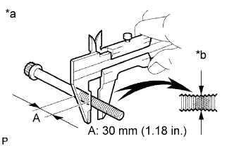
Text in Illustration *a Measuring Point *b Compressed Thread
-
Using a vernier caliper, measure the minimum outside diameter of the compressed thread at the measuring point A.
Standard outside diameter 11.76 to 11.97 mm (0.463 to 0.471 in.) Minimum outside diameter 11.6 mm (0.457 in.) If the outside diameter is less than the minimum, replace the bolt.
-
-
INSPECT CAMSHAFT
-
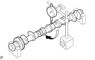
Inspect the circle runout.
-
Place the camshaft on V-blocks.
-
Using a dial indicator, measure the circle runout.
Maximum circle runout 0.03 mm (0.0012 in.) If the circle runout is greater than the maximum, replace the camshaft.
-
-
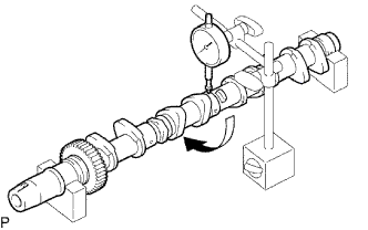
Inspect the cam lobe height.
-
Using a micrometer, measure the cam lobe height.
Standard cam lobe height 47.180 to 47.280 mm (1.8575 to 1.8614 in.) Minimum cam lobe height 46.760 mm (1.8409 in.) If the cam lobe height is less than the minimum, replace the camshaft.
-
-
Inspect the journal diameter of the camshaft.
-
Using a micrometer, measure the journal diameter of the camshaft bearing.
Standard journal diameter 27.969 to 27.985 mm (1.1011 to 1.1018 in.) If the journal diameters is not as specified, check the oil clearance.
-
-
Check the oil clearance.
-
Clean the bearing caps and journals.
-
Check the bearings for flaking and scoring.
If the bearings are damaged, replace the bearing caps and cylinder head as a set.
-
Install the bearings to the bearing caps and cylinder head.
-
Place the camshaft on the cylinder head.
-
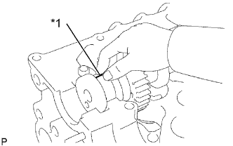
Lay a strip of Plastigage across each of the journals.
Text in Illustration *1 Plastigage -
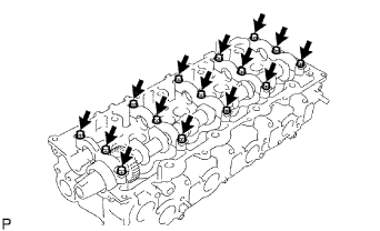
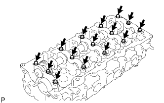
Install the bearing caps.
Note
Do not turn the camshaft.
-
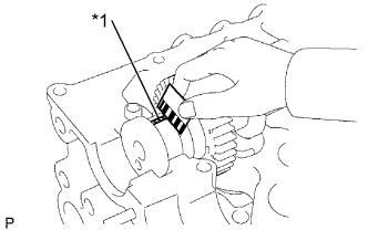
Remove the bearing caps.
-
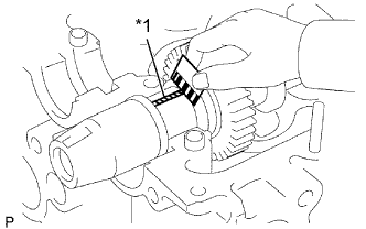
Text in Illustration *1 Plastigage Measure the Plastigage at its widest point.
Standard oil clearance 0.025 to 0.062 mm (0.0010 to 0.0024 in.) Maximum oil clearance 0.10 mm (0.0039 in.) If the oil clearance is greater than the maximum, replace the camshaft. If necessary, replace the bearing caps and cylinder head as a set.
-
Completely remove the Plastigage.
-
Remove the camshaft. Click here
-
-
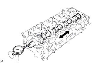
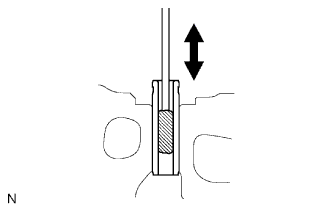
Check the thrust clearance.
-
Install the camshaft. Click here
-
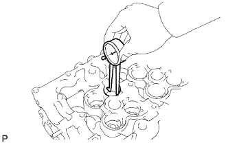
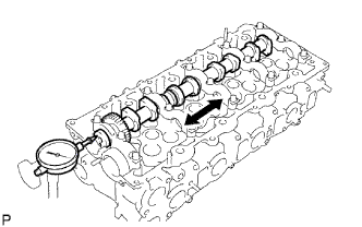
Using a dial indicator, measure the thrust clearance while moving the camshaft back and forth.
Standard thrust clearance 0.035 to 0.185 mm (0.0014 to 0.0073 in.) Maximum thrust clearance 0.25 mm (0.0098 in.) If the thrust clearance is greater than the maximum, replace the camshaft. If necessary, replace the bearing caps and cylinder head as a set.
-
-
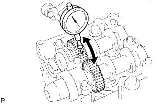
Using a dial indicator, measure the backlash.
-
Install the 2 camshafts.
-
Using a dial indicator, measure the backlash.
Standard backlash 0.035 to 0.089 mm (0.0014 to 0.0035 in.) Maximum backlash 0.189 mm (0.0074 in.) If the backlash is greater than the maximum, replace the camshaft.
-
Remove the 2 camshafts. Click here
-
-
-
INSPECT NO.2 CAMSHAFT
-
Inspect the circle runout.
-
Place the camshaft on V-blocks.
-
Using a dial indicator, measure the circle runout.
Maximum circle runout 0.03 mm (0.0012 in.) If the circle runout is greater than the maximum, replace the camshaft.
-
-
Inspect the cam lobe height.
-
Using a micrometer, measure the cam lobe height.
Standard cam lobe height 48.071 to 48.171 mm (1.8925 to 1.8965 in.) Maximum cam lobe height 47.920 mm (1.8866 in.) If the cam lobe height is less than the minimum, replace the camshaft.
-
-
Inspect the journal diameter of the camshaft.
-
Using a micrometer, measure the journal diameter of the camshaft bearing.
Standard journal diameter 27.969 to 27.985 mm (1.1011 to 1.1018 in.) If the journal diameters is not as specified, check the oil clearance.
-
-
Check the oil clearance.
-
Clean the bearing caps and journals.
-
Check the bearings for flaking and scoring.
If the bearings are damaged, replace the bearing caps and cylinder head as a set.
-
Install the bearings to the bearing caps and cylinder head.
-
Place the camshaft on the cylinder head.
-
Lay a strip of Plastigage across each of the journals.
Text in Illustration *1 Plastigage -
Install the bearing caps.
Note
Do not turn the camshaft.
-
Remove the bearing caps.
-
Text in Illustration *1 Plastigage Measure the Plastigage at its widest point.
Standard oil clearance 0.025 to 0.062 mm (0.0010 to 0.0024 in.) Maximum oil clearance 0.10 mm (0.0039 in.) If the oil clearance is greater than the maximum, replace the camshaft. If necessary, replace the bearing caps and cylinder head as a set.
-
Completely remove the Plastigage.
-
Remove the camshaft. Click here
-
-
Check the thrust clearance.
-
Install the camshaft. Click here
-
Using a dial indicator, measure the thrust clearance while moving the camshaft back and forth.
Standard thrust clearance 0.035 to 0.185 mm (0.0014 to 0.0073 in.) Maximum thrust clearance 0.25 mm (0.0098 in.) If the thrust clearance is greater than the maximum, replace the camshaft. If necessary, replace the bearing caps and cylinder head as a set.
-
Remove the camshafts. Click here
-
-