CRANKSHAFT POSITION SENSOR (w/ DPF) INSTALLATION

-
INSTALL CRANKSHAFT POSITION SENSOR
-
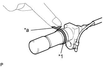
Text in Illustration *1 O-ring *a Engine Oil Apply a light coat of engine oil to the O-ring of the crankshaft position sensor.
-
TYPE A:
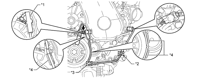
Text in Illustration *1 Clamp *2 Wire Harness Clamp (A) *3 Wire Harness Clamp (B) *4 Protrusion
-
Install the crankshaft position sensor with the bolt.
- Torque:
- 8.5 N*m { 87 kgf*cm, 75 in.*lbf }
Note
Make sure that the O-ring is not damaged or does not jump out of position during installation.
-
Install a new clamp.
Note
-
Make sure that no portion of the clamp remains in the clamp installation hole. If there is any portion of the clamp remaining, remove it.
-
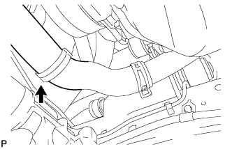
Make sure the crankshaft position sensor wire harness is installed in the position shown in the illustration.
-
-
Attach the crankshaft position sensor connector to the No. 1 vacuum transmitting pipe.
-
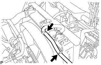
Connect the crankshaft position sensor connector.
-
Attach the 2 wire harness clamps (A, B).
-
-
TYPE B:
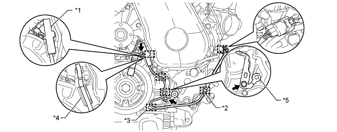
Text in Illustration *1 Clamp *2 Wire Harness Clamp (A) *3 Wire Harness Clamp (B) *4 Protrusion *5 Bracket (Clamp) - -
-
Install the crankshaft position sensor with the bolt.
- Torque:
- 8.5 N*m { 87 kgf*cm, 75 in.*lbf }
Note
Make sure that the O-ring is not damaged or does not jump out of position during installation.
-
Install the bracket (clamp) with the bolt.
- Torque:
- 13 N*m { 132 kgf*cm, 9.5 ft.*lbf }
-
Install a new clamp.
Note
-
Make sure that no portion of the clamp remains in the clamp installation hole. If there is any portion of the clamp remaining, remove it.
-
Make sure the crankshaft position sensor wire harness is installed in the position shown in the illustration.
-
-
Attach the crankshaft position sensor connector to the No. 1 vacuum transmitting pipe.
-
Connect the crankshaft position sensor connector.
-
Attach the 2 wire harness clamps (A, B).
-
Attach the 2 wire harness clamps to the bracket (clamp).
-
-
-
INSTALL FAN PULLEY
-
Install the fan pulley onto the water pump.
-
-
INSTALL FAN SHROUD
-
Temporarily install the fan shroud together with the fan with fluid coupling.
-
Install the fan shroud with the 2 bolts.
- Torque:
- 7.0 N*m { 71 kgf*cm, 62 in.*lbf }
-
Connect the outlet radiator hose onto the fan shroud.
-
Connect the reserve tank hose onto the fan shroud.
-
-
TEMPORARILY TIGHTEN FLUID COUPLING ASSEMBLY
-
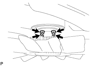
Temporarily tighten the fluid coupling with the 4 nuts.
-
Install the fan and generator V belt Click here.
-
Fully tighten the 4 nuts.
- Torque:
- 23 N*m { 235 kgf*cm, 17 ft.*lbf }
-
-
INSTALL FAN AND GENERATOR V BELT (W/O AIR CONDITIONING)
-
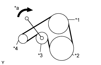
Use the pulley set bolt of the tensioner to rotate the tensioner pulley clockwise, and then install the V belt.
Text in Illustration *1 Fan Pulley *2 Crankshaft *3 Tensioner *4 Generator *a Turn Note
Make sure that the V belt is set properly at each pulley.
-
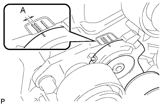
Make sure that the indicator mark of the tensioner is within range A, as shown in the illustration.
-
-
INSTALL FAN AND GENERATOR V BELT (W/ AIR CONDITIONING)
-
Use the pulley set bolt of the tensioner to rotate the tensioner pulley clockwise, and then install the V belt.
Text in Illustration *1 Fan Pulley *2 Crankshaft *3 Tensioner *4 Generator *a Turn Note
Make sure that the V belt is set properly at each pulley.
-
Make sure that the indicator mark of the tensioner is within range A, as shown in the illustration.
-
-
TIGHTEN FLUID COUPLING ASSEMBLY
-
INSTALL INLET RADIATOR HOSE
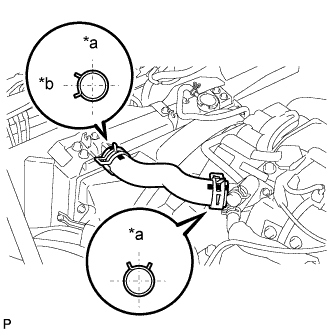
Text in Illustration *a Upper *b Left
-
Install the inlet radiator hose, as shown in the illustration, with the 2 hose clamps.
-
-
ADD ENGINE COOLANT
-
Pour coolant into the radiator until it overflows.
Capacity Specification Capacity w/o Heater 9.8 liters (10.3 US qts, 8.6 Imp. qts) w/ Front Heater 10.7 liters (11.3 US qts, 9.4 Imp. qts) w/ Front and Rear Heater 11.5 liters (12.2 US qts, 10.1 Imp. qts) Note
Do not substitute plain water for engine coolant.
Tech Tips
-
Use of improper coolants may damage the engine cooling system.
-
Use only Toyota Super Long Life Coolant or similar high quality ethylene glycol based non-silicate, non-amine, non-nitrite, and non-borate coolant with long-life hybrid organic acid technology (coolant with long-life hybrid organic acid technology consists of a combination of low phosphates and organic acids).
-
-
Check the coolant level inside the radiator by squeezing the inlet and outlet radiator hoses several times by hand.
If the coolant level goes down, add coolant.
-
Install the radiator cap securely.
-
Slowly pour coolant into the radiator reservoir until it reaches the FULL line.
-
Warm up the engine until the thermostat opens.
-
While the thermostat is open, circulate the coolant for several minutes.
Tech Tips
The thermostat open timing can be confirmed by pressing the inlet radiator hose by hand, and checking when the engine coolant starts to flow inside the hose.
-
-
Maintain the engine speed at 2000 to 2500 rpm.
-
Squeeze the inlet and outlet radiator hoses several times by hand while warming up the engine to bleed the air.
CAUTION:
-
Wear protective gloves.
-
Be careful as the radiator hoses are hot.
-
Keep your hands away from the fan.
When squeezing the radiator hoses:
-
-
Stop the engine and wait until the coolant cools down.
-
Remove the radiator cap and check the coolant level inside the radiator.
-
If the coolant level is below the full level, repeat the operation until the coolant level remains at the full level.
-
Check the coolant level inside the radiator reservoir tank again.
If it is below the full level, add coolant.
-
-
INSPECT FOR COOLANT LEAK
-
Remove the radiator cap.
CAUTION:
To avoid the danger of being burned, do not remove the radiator cap while the engine and radiator are still hot. Thermal expansion will cause hot engine coolant and steam to blow out from the radiator.
-
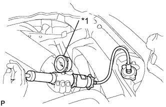
Text in Illustration *1 Radiator Cap Tester Fill the radiator with coolant and attach a radiator cap tester.
-
Warm up the engine.
-
Pump it to 118 kPa (1.2 kgf/cm2, 17.1 psi), then check that the pressure does not drop.
If the pressure drops, check the hoses, radiator and water pump for leakage. If there are no signs of external coolant leakage, check the heater core, cylinder block and head.
-
Reinstall the radiator cap.
-
-
INSPECT FOR OIL LEAK
-
Warm up the engine and inspect for oil leak.
-
-
INSTALL ENGINE SERVICE HOLE SUB COVER SUB-ASSEMBLY (for Double Cab)