CRANKSHAFT POSITION SENSOR (w/ DPF) REMOVAL

-
REMOVE ENGINE SERVICE HOLE SUB COVER SUB-ASSEMBLY (for Double Cab)
-
DRAIN ENGINE COOLANT
CAUTION:
To avoid the danger of being burned, do not remove the radiator cap while the engine and radiator are still hot. Thermal expansion will cause hot engine coolant and steam to blow out from the radiator.
-
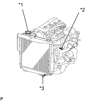
Text in Illustration *1 Radiator Cap *2 Engine Drain Plug *3 Radiator Drain Plug Loosen the radiator drain plug (on the radiator).
-
Remove the radiator cap.
-
Loosen the engine drain plug (on the oil cooler cover), and drain the coolant.
-
Drain the coolant from the reservoir tank.
-
Tighten the engine drain plug.
- Torque:
- 8.0 N*m { 82 kgf*cm, 71 in.*lbf }
-
-
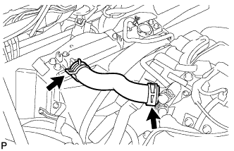
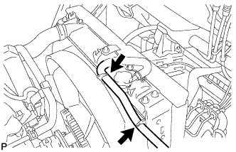
REMOVE INLET RADIATOR HOSE
-
Disconnect the 2 hose clamps and remove the inlet radiator hose.
-
-
LOOSEN FLUID COUPLING ASSEMBLY
-
REMOVE FAN AND GENERATOR V BELT (w/o Air Conditioning System)
-
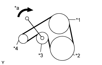
Text in Illustration *1 Fan Pulley *2 Crankshaft *3 Tensioner *4 Generator *a Turn Using the pulley set bolt of the tensioner, rotate the tensioner pulley clockwise to loosen the belt's tension. Then remove the V belt.
-
-
REMOVE FAN AND GENERATOR V BELT (w/ Air Conditioning System)
-
Text in Illustration *1 Fan Pulley *2 Crankshaft *3 Tensioner *4 Generator *a Turn Using the pulley set bolt of the tensioner, rotate the tensioner pulley clockwise to loosen the belt's tension. Then remove the V belt.
-
-
REMOVE FLUID COUPLING ASSEMBLY
-
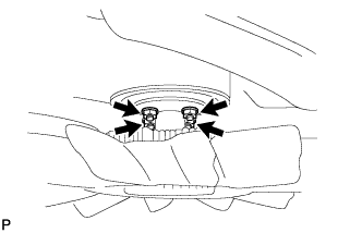
Loosen the 4 nuts from the fan pulley.
-
Remove the fan and generator V belt Click here.
-
Remove the 4 nuts.
-
-
REMOVE FAN SHROUD
-
Disconnect the reserve tank hose from the fan shroud.
-
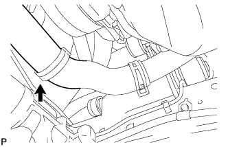
Disconnect the outlet radiator hose from the fan shroud.
-
Remove the 2 bolts and separate the the fan shroud.
-
Remove the fan with fluid coupling and fan shroud.
-
-
REMOVE FAN PULLEY
-
Remove the fan pulley from the water pump.
-
-
REMOVE CRANKSHAFT POSITION SENSOR
-
TYPE A:
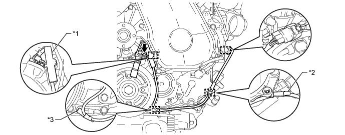
Text in Illustration *1 Clamp *2 Wire Harness Clamps (A) *3 Wire Harness Clamps (B) - -
-
Detach the 2 wire harness clamps (A, B).
-
Disconnect the crankshaft position sensor connector.
-
Detach the crankshaft position sensor connector from the No. 1 vacuum transmitting pipe.
-
Remove the clamp.
Note
-
Make sure that no portion of the clamp remains in the clamp installation hole. If there is any portion of the clamp remaining, remove it.
-
Do not reuse the clamp.
-
-
Remove the bolt and crankshaft position sensor.
-
-
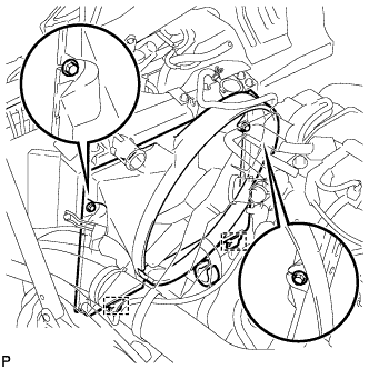
TYPE B:
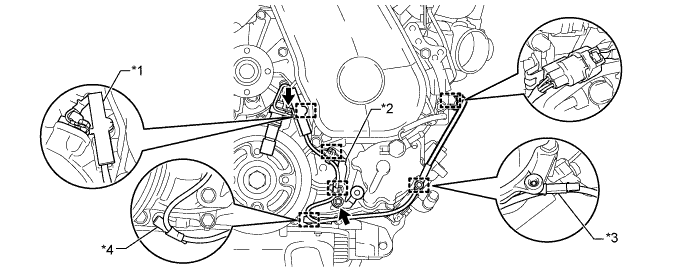
Text in Illustration *1 Clamp *2 Bracket (Clamp) *3 Wire Harness Clamps (A) *4 Wire Harness Clamps (B)
-
Detach the 2 wire harness clamps (A, B).
-
Disconnect the crankshaft position sensor connector.
-
Detach the crankshaft position sensor connector from the No. 1 vacuum transmitting pipe.
-
Remove the clamp.
Note
-
Make sure that no portion of the clamp remains in the clamp installation hole. If there is any portion of the clamp remaining, remove it.
-
Do not reuse the clamp.
-
-
Remove the bolt and bracket (clamp).
-
Remove the bolt and crankshaft position sensor.
-
Detach the 2 wire harness clamps from the bracket (clamp).
-
-