ECD SYSTEM DTC CHECK / CLEAR
-
DTC CHECK / CLEAR
-
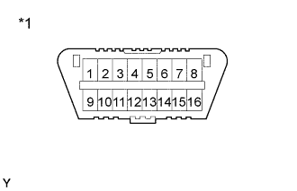
Text in Illustration *1 DLC3 Check the DLC3.
The vehicle's ECM uses ISO 14230 for communication. The terminal arrangement of the DLC3 complies with SAE J1962 and matches the ISO 14230 format.
Terminal No. Connection/Voltage or Resistance Condition 7 Bus + Line/Pulse generation During transmission 4 Chassis Ground ←→ Body Ground/1 Ω or less Always 16 Battery Positive ←→ Body Ground/9 - 14 V Always Tech Tips
If your display shows UNABLE TO CONNECT TO VEHICLE when you have connected the cable of the intelligent tester to the DLC3, turned the ignition switch ON and operated the intelligent tester, there is a problem on the vehicle side or tool side.
-
If communication is normal when the tool is connected to another vehicle, inspect the DLC3 on the original vehicle.
-
If communication is still not possible when the tool is connected to another vehicle, the problem is probably in the tool itself, so consult the Service Department listed in the tool's instruction manual.
-
-
-
INSPECT DIAGNOSIS (Normal Mode)
-
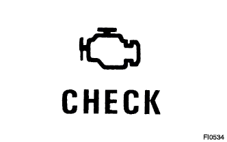
Check the check engine warning light.
-
The check engine warning light comes on when the ignition switch is turned ON and the engine is not running.
Tech Tips
If the check engine warning light does not light up, troubleshoot the combination meter.
-
When the engine is started, the check engine warning light should go off. If the lamp remains on, the diagnosis system has detected a malfunction or abnormality in the system.
-
-
Check the DTC using intelligent tester.
Note
When the diagnosis system is switched from the normal mode to the check (test) mode, it erases all DTCs and freeze frame data recorded in the normal mode. So before switching modes, always check the DTCs and freeze frame data, and note them down.
-
Prepare the intelligent tester.
-
Connect the intelligent tester to the DLC3.
-
Turn the ignition switch ON and switch the intelligent tester main switch ON.
-
Use the intelligent tester to check the DTCs and freeze frame data, note them down. (for operating instructions, see the intelligent tester's instruction book.)
-
Confirm the details of the DTCs.
-
-
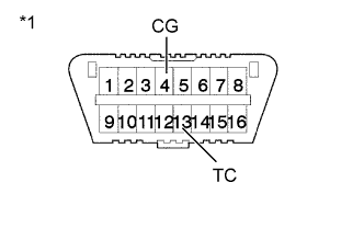
Text in Illustration *1 DLC3 Check the DTC not using intelligent tester.
-
Turn the ignition switch ON.
-
Using SST, connect between terminals 13 (TC) and 4 (CG) of the DLC3.
- SST
- 09843-18040
-
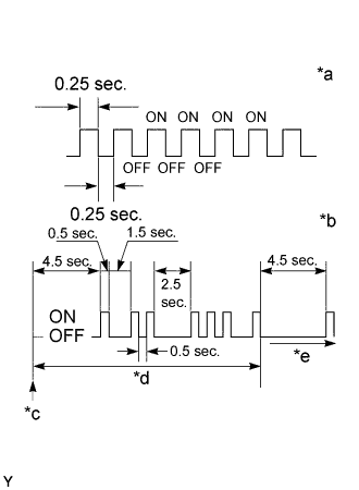
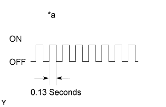
Text in Illustration *a Normal *b 12 and 31 *c Start *d One Cycle *e Repeat Read the DTC from the check engine warning light. As an example, the blinking patterns for codes; normal, 12 and 31 are as shown in the illustration.
Tech Tips
If a DTC is not output, check the diagnostic connector (DLC3) circuit Click here.
-
Check the details of the malfunction using the DTC chart on page Click here.
-
After completing the check, disconnect terminals 13 (TC) and 4 (CG) and turn off the display.
Tech Tips
In the event of 2 or more malfunction codes, the indication will begin from the smaller numbered code to the larger in order.
Note
When simulating symptoms without a intelligent tester to check the DTCs, use the normal mode. For code on the DTCs chart subject to "2 trip detection logic", turn the ignition switch OFF after the symptom is simulated the first time. Then repeat the simulation process again. When the problem has been simulated twice, the check engine warning light lights up and the DTCs are recorded in the ECM.
-
-
-
INSPECT DIAGNOSIS (Check (Test) Mode)
intelligent tester only:
Compared to the normal mode, the check mode has an increased sensitivity to detect malfunctions.
Furthermore, the same diagnostic items which are detected in the normal mode can also be detected in the check (test) mode.
-
Check the DTC.
-
Initial conditions.
-
Battery positive voltage 11 V or more
-
Throttle valve fully closed
-
Transmission in neutral position
-
A/C switched OFF.
-
-
Turn the ignition switch OFF.
-
Prepare the intelligent tester.
-
Connect the intelligent tester to the DLC3.
-
Turn the ignition switch ON and push the intelligent tester main switch ON.
-
Text in Illustration *a Flashing Switch the intelligent tester from the normal mode to the check (test) mode. (Check that the check engine warning light flashes.)
-
Start the engine. (The check engine warning light goes out after the engine start.)
-
Simulate the conditions of the malfunction described by the customer.
Note
Leave the ignition switch ON until you have checked the DTCs, etc.
-
After simulating the malfunction conditions, use the intelligent tester diagnosis selector to check the DTCs and freeze frame data, etc.
Tech Tips
Take care not to turn the ignition switch OFF. Turning the ignition switch OFF switches the diagnosis system from the check (test) mode to the normal mode, so all diagnostic codes, etc. are erased.
-
After checking the DTCs, inspect the applicable circuit.
-
-
Clear the DTC.
The following actions will erase the DTCs and freeze frame data.
-
Operating the intelligent tester to erase the codes. (See the intelligent tester's instruction book for operating instructions.)
-
Disconnecting the battery terminals or ECD fuse.
Note
If the intelligent tester switches the ECM from the normal mode to the check (test) mode or vice-versa, or if the ignition switch is turned from ON to ACC or OFF during the check (test) mode, the DTCs and freeze frame data will be erased.
-
-